Signalling
Part:BBa_F2620:Response time
Designed by: Barry Canton [bcanton@mit.edu] and Anna Labno [labnoa@mit.edu] Group: iGEM04_MIT (2004-08-09)
(Redirected from Part:BBa F2620:Latency)
|
|
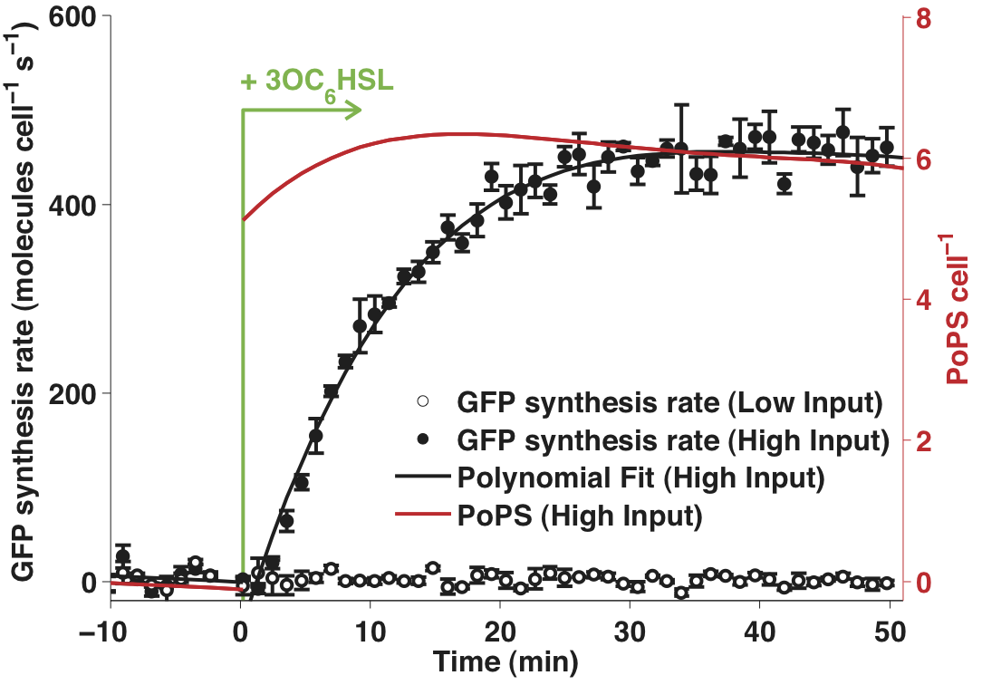
Response time measures the characteristic time taken for the output of a system to respond to a change in input. We chose to measure the response of BBa_F2620 to a step increase from low to high in the input signal (3OC6HSL). Please see the part experience page for a general description of our characterization method.
Data

Figure 1 - Time response of BBa_T9002 to a step increase in input concentration from 0 to 100 nM AHL. The mean GFP synthesis rates measured for three cultures of the composite part (BBa_T9002) are shown as filled (high input) or empty (low input) circles. Error bars represent standard deviations across the independent cultures. The solid black lines are a linear fit to the data. The time dependent PoPS output from the receiver (shown as a solid red line) was calculated using a model of the dynamic behavior of the reporter device.
| Data | Notes | Date Uploaded |
|---|---|---|
| File:BC-Latency-4.txt | Raw data for T9002 and the T9002 mutant with no GFP expression device. | 01/15/07 |
Protocol
- Two cultures, one of MG1655 bearing BBa_T9002 and one of MG1655 bearing the BBa_T9002 mutant lacking a GFP expression device (see stability section) were prepared as described in steps 1 – 3 of the transfer function protocol.
- Six 200 µl aliquots of the BBa_T9002 culture were transferred into a flat-bottom 96 well plate.
- Three wells were each filled with 200 μl of medium to measure the absorbance background. Three further wells were each filled with 200 μl of the BBa_T9002 mutant culture to measure fluorescent background. 3OC6HSL was added to three of the wells containing the BBa_T9002 culture to a final concentration of 1E-7 M.
- The plate was incubated in a [http://openwetware.org/wiki/Endy:Victor3_plate_reader Wallac Victor3 multi-well fluorimeter] at 37°C and assayed with an automatically repeating protocol of fluorescence measurements, absorbance measurements, and shaking (all as described in the transfer function protocol). Time between repeated measurements was 54 s.
- Data processing is described on the Data analysis page. The short interval between measurements resulted in apparent noise in the calculated GFP synthesis rates. Thus, the time response data shown in Figure 1 had an additional processing step in which the raw fluorescence data was smoothed using [http://mathworks.com MATLAB’s], rlowess smoothing filter across five time points. The same data, processed without the smoothing filter, is shown in Figure 2. In both Figure 1 and Figure 2, the error bars represent the 95% confidence interval for the mean.
- The low-to-high (LH) response time of the device was parameterized by calculating the time taken for the output to rise to 50% and 90% of its maximum value. These times were calculated by linearly interpolating between the measured data values.

 1 Registry Star