Part:BBa_I732005:Experience
This experience page is provided so that any user may enter their experience using this part.
Please enter
how you used this part and how it worked out.
Applications of BBa_I732005
UI Indonesia iGEM team 2013 improve the function of this part by expressing lacZ gene in two separate fragment (BBa_K1182425, the α fragment) and (BBa_K1182000, the ω fragment). These two fragments can interact with each other and still own the enzymatic activity of β galactosidase.
The Genspace 2015 iGEM team made a Lux + LacZ device (BBa_K1799019) in order to evaluate a prototype biosensor that detects L-Acyl-Homoserine-Lactone (AHL) and produces beta galactosidase activity in response. This mechanism is as follows: AHL is a small molecule (213.23 Daltons) produced by some bacteria that have evolved quorum sensing circuits to detect the presence of high concentrations of bacteria. We started with the naturally-occurring quorum-sensing circuit wherin the LuxR regulatory protein binds with AHL and stimulates promotion by the pLux promoter. In the wild, this can trigger behavior such as biofilm formation. Placement of the LacZ translational unit downstream of the pLux results in the production of beta galactosidase in the presence of AHL. This can be measured using the Miller Assay.
The Lux pathway responds to the presence of AHL, which is produced by various bacterial species, including Pseudomonas aeruginosa, commonly found in large numbers in human waste and sewage.
Experimental Data
A Beta-Galactosidase Assay (aka “Miller Assay”) was carried out as described by Marian Price-Carter from the Roth Lab at UCLA (http://rothlab.ucdavis.edu/protocols/beta-galactosidase-3.html). Different concentrations of AHL were found to impact both cell growth profiles as well as Beta-Galactosidase activity levels. We also found that constant exposure to high levels of AHL (1uM) through repeated 1:100 dilutions had no discernable impact on cell growth compared to negative controls (0uM), but had the unexpected effect of minimizing Beta-Galactosidase production – even relative to negative controls. Indeed, we found the unit-step change in AHL concentration to be the salient factor in increased expression of Beta-Galactosidase. By “unit-step” change, we mean making a 1:100 dilution from an overnight with no AHL into an LB solution with the appropriate antibiotics and a greater-than-zero AHL concentration.
The AHL concentrations reported here were determined based on initial attempts to find a concentration range where cell growth was neither substantially delayed nor was Beta-Galactosidase production only modestly increased. We started with overnights that were first prepared in 0uM and 1uM AHL concentrations with appropriate antibiotics in LB media in a rotating incubator at 37C. The 1uM AHL overnight was diluted 1:100 into fresh LB media with appropriate antibiotics and with 1uM AHL to serve as the positive control. The overnight with no AHL was diluted 1:100 into fresh LB media with appropriate antibiotics and either 0uM or 1uM AHL. The 0nM AHL solution served as the negative control. Each hour after dilution (for a total of four hours), 1 mL samples were taken and immediately evaluated for OD600 readings as well as input to the Beta-Galactosidase assay. The initial results are shown below (note: not in triplicate at this stage of the experiment).
 Initial Cell Density & Beta-Galactosidase Activity versus Time
We were intrigued by the low rate of growth for the 1uM test case as well as the considerable Beta-Galactosidase activity levels. We wished to find the AHL concentrations that resulted in reduced amounts of delay in cell growth through a series of OD600 measurements (which are easier to conduct than a Beta-Galactosidase assay). In a similar way as before, we evaluated the following AHL concentrations in succession: 1uM (1000nM), 500nM, 100nM, 10nM, 3nM, 1nM, 0.5nM and the results are shown in the figure below.
 Preliminary Cell Density Studies
All AHL concentrations greater than 10nM showed consistent delays in cell growth over the first three or four hours. Concentrations between 0.5nM and 10nM showed an almost uniform variation between minimal and maximal delay, respectively. Guided by this preliminary investigation, and consistent with previous characterizations involving the Lux promoter (for example, see https://parts.igem.org/Part:BBa_R0062:Experience ), we chose to focus on unit-step AHL concentrations of 0.1nM, 1nM and 10nM. A negative control with no AHL and a positive control maintained in 1uM AHL continued to be included for comparative purposes. Overnights were first prepared in 0uM and 1uM AHL concentrations with appropriate antibiotics in LB media in a rotating incubator at 37C. The 1uM AHL overnight was diluted 1:100 into fresh LB media with appropriate antibiotics and with 1uM AHL to serve as the positive control. The overnight with no AHL was diluted 1:100 into fresh LB media with appropriate antibiotics and either 0nM, 0.1nM, 1nM or 10nM AHL. The 0nM AHL solution served as the negative control. Each hour after dilution, 1.5 mL samples were taken and put immediately on ice and stored at 4C to create triplicate 0.5mL samples for use in the Beta-Galactosidase assay.
Cell growth curves as measured by OD600 were obtained and are plotted below.

There is no substantial difference between the positive and negative controls. The growth curve associated with the 0.1nM solution is also substantially the same as the controls. In contrast, the growth curves for 1nM and 10nM are considerably delayed compared to the controls. However, after 14 hours, all solutions under study have approached stationary phase.
The Beta-Galactosidase Activity (measured in Miller Units) is plotted below.

As observed in prior work (e.g., http://www.ncbi.nlm.nih.gov/pmc/articles/PMC3145315/) the high levels (>20,000) of Beta-Galactosidase activity associated with AHL concentrations of 1nM and 10nM are correlated with delayed cell growth. While the negative control has a relatively low level of Beta-Galactosidase activity, as expected, it is remarkable to note that the positive control has a lower level still. In a quorum sensing context, we might make sense of this as follows: the constant presence of a high-level of AHL does not require the same action as a sudden change in AHL. In this case, some refractory mechanism would appear reasonable. The unit-step change of AHL concentration to 0.1nM results in increased activity that attenuates to negative control levels after approximately 5 hours, consistent with being on the low-end of the AHL scale. In contrast, the 1nM and 10nM concentrations of AHL result in dramatic increases in activity. The onset of activity increase for 1nM appears to be slightly delayed compared to 10nM, which could be related to the effective diffusion delay of AHL through the outer membrane pores. However, after 3 hours, the activity for 1nM is commensurate with 10nM and eventually is greater beyond hour 8. This is due to an intrinsic difference in behavior as a function of AHL concentration that is explored next.
The number of Beta-Galactosidase molecules at each hour is estimated by multiplying the Miller Units (a reasonable proxy for the number of Beta-Galactosidase molecules per cell as noted by Garcia et al., 2011) by the OD600 value scaled by 8x10⁸. Using a three-sample moving average to ride out statistical fluctuations in each time series, we find the results shown below.

This plot shows that the concentration of 1nM AHL results in the highest yield of Beta-Galactosidase, almost a factor of four times greater than the negative control. These results are of interest in a variety of applications where the total yield of a synthesized product must be either maximized or set to a target value (often subject to a variety of other constraints). Further consideration of this type of phenomena is considered in the figures below.

The yield curves in these concentrations under study have a number of features in common. The yield over the first three hours increases at the lowest rate (r1). After three hours, the rate often increases (r2>r1) until a plateau is reached (P). These three parameters (r1, r2 and P) are sufficient to classify the observed yield curves. In the case of the positive and negative controls – as well as the 0.1nM concentration – the plateau is reached about an hour after entering stationary phase. This may also be true for the 10nM concentration as 14 hours of data capture was barely sufficient to reach stationary phase. However it is noteworthy that the 1nM concentration appears to have reached its plateau of terminal yield after only 11 hours (i.e., even while still in mid-log growth).
User Reviews
Introduction
For the electrochemical detection system to achieve its full potential, various conditions needed to be optimized for our purposes. These included the buffer solution present and the type of electrode plating used. The final conditions will be incorporated into the field-ready kit that can be used by anyone with minimal training.
Buffer Solutions
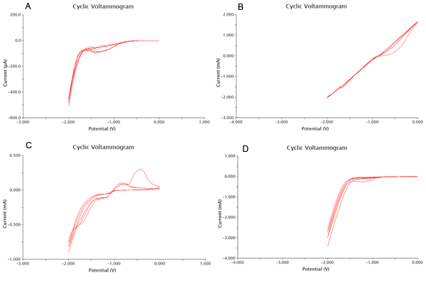
We tested 11 potential buffering systems to find the optimal graph for chlorophenol red detection. The hallmark of a good buffer is one that can conduct a current effectively and has no species present that will undergo a redox reaction at the voltage you are measuring. For our project, we were looking at an oxidation reaction at -0.7V on our detection system. A good buffer for us will have a consistent flat line between -1V and -0.5V. Another feature of a good buffer is that the difference between the cathodic and anodic sweeps is not large. This is easy to notice, as the larger the difference, the bigger the gap between upper and lower lines during the flat section around 0V. The results of our buffer screens are shown in Figure 1 and Figure 2.
Based on the results show above, 0.1M CaCl2 was the best buffering system, as it had consistently flat areas through the testing range and conducted large currents. It was also shown that acetonitrile at 0.01% was the worst solvent, and it caused massive electrode degradation during the test runs.
Plating Methods
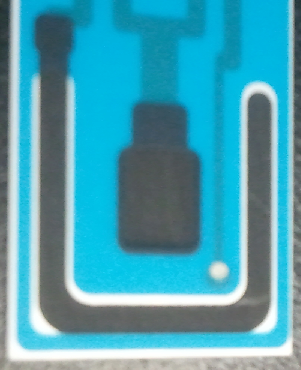
When an electrode is plated with a metal, the metal can participate in redox reactions to release or absorb electrons and conduct a current. This can enhance the resolution of an electrode and produce more easily interpretable results. One important example of plated electrodes is that found for silver/silver chloride electrodes. The silver atoms from the silver chloride can absorb an electron and become silver metal. Due to the nature of this reaction and that it is highly characterized, it can be used as a reference electrode, and is shown as a small silver disk on our electrodes.
We tested a variety of common electroplating metals, including platinum, zinc, nickel, and copper. The results of our tests are shown below in Figure 4. From this data we concluded that nickel plating our electrodes was the best choice, and have included nickel in all of our electrochemistry procedures. This was chosen due to the decrease in size between the cathodic and anodic sweeps, as well as some decreased noise from extraneous species in the buffer. The only other plating method close to NiSO4 was zinc thiocyanate, however this electroplating method had a peak that had higher overlap with the voltage range to be tested.
Detection
Now that we have determined the best buffer and plating methods, we need to start testing our samples. To do this we have used cyclic voltammetry to measure the change in current over a range from -2V to 2V. We performed this sweep 6 times, which would mean that there are 3 cathodic and 3 anodic sweeps. This gives us our data in triplicate. We performed our sweeps at a speed of 100mV/s to increase the amount of data collected and the resoultion of our scans. After this the collected data was processed as shown in the appendix. One extremely important data point we obtained was the number of cells needed to produce optimal results. With more cells the current could be disrupted, and with less cells not enough could be produced.
Results
The final results of our data processing is shown in Figure 1 below. The calculations done to arrive at this final curve are in the appendix.
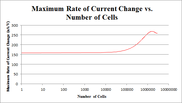
By repeating this procedure for the various tested cell levels, we can construct one of our standard curves - the maximum rate of current change versus number of cells.
We determined the concentration of cells in our culture to be 7.35*108 cells/mL. For the purposes of making a biosensor, we can see that having 105 to 107 cells in our electrochemical system provides a strong signal, while not risking saturating our detection mechanism. This is completely feasible with a small amount of our cell culture.
Appendix
In order to construct our standard curve for current response vs. number of cells, several experiments were conducted with varying numbers of cells, with a constant amount of CPRG (100uL at 0.5M), NaH2PO4 buffer (1mL at 0.5M), and nanopure water (up to 20mL). The cell was left for 5 minutes before the experiment was run.
Figure 2 below shows experimental data for a cyclic voltammetry experiment done with 7.5*105 cells.
We observe the characteristic dip indicative of CPR oxidation at approximately -0.71V, showing the presence of CPR in solution. Next, the time derivative of this curve will be taken, shown below.
Using Figure 3, we determine the maximum rate of change of current to occur at -0.755V, with a maximum of 258.45uA/V.
By repeating this procedure for the various tested cell levels, we can construct one of our standard curves - the maximum rate of current change versus number of cells.
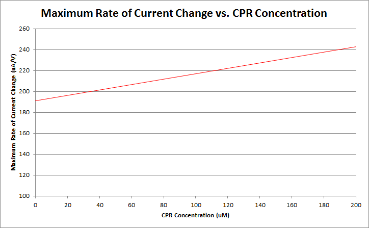
Finally, by varying the amount of CPR in solution, and running cyclic voltammetry experiments in a simple system of only CPR, buffer, and nanopure water, we can construct a standard curve of CPR concentration versus maximum rate of current change. This graph is shown below.
Currently, work is being done to refine our ability to differentiate between varying levels of CPR concentration. Our preliminary data is shown below.
UNIQ1ad4648801fa7313-partinfo-0000000B-QINU
|
•••••
Lri |
This part was used as a reporter. It performed as expected. β-gal assays showed that this part was expressed in the expected pattern and was useful as a reporter. |
UNIQ1ad4648801fa7313-partinfo-0000000D-QINU

 1 Registry Star


