Part:BBa_K2598039
YF1+fixJ+PhIF
This parts contains yellow-light ensor TF1 and fixJ along with repressor PhIFunder their regulation.Together they can serve as a sensor triggered by yellow light. It is part of the GRB system, see more information from RGB System
Sequence and Features
- 10COMPATIBLE WITH RFC[10]
- 12COMPATIBLE WITH RFC[12]
- 21COMPATIBLE WITH RFC[21]
- 23COMPATIBLE WITH RFC[23]
- 25INCOMPATIBLE WITH RFC[25]Illegal NgoMIV site found at 587
Illegal NgoMIV site found at 659
Illegal NgoMIV site found at 749
Illegal NgoMIV site found at 767
Illegal NgoMIV site found at 1259
Illegal NgoMIV site found at 1552
Illegal NgoMIV site found at 1646
Illegal AgeI site found at 301
Illegal AgeI site found at 1427 - 1000INCOMPATIBLE WITH RFC[1000]Illegal BsaI site found at 1316
Illegal BsaI.rc site found at 200
Characterization
Figure 1 shows the relationship between the wavelength of light exposed on liquid medium and the intensity of BFP, GFP and RFP E. coli expressed from left figure to right figure respectively. We got the data through flow cytometer and analyzed it to get the figure. The y-axis is the number of cells, and the x-axis is fluorescence intensity. And every color is E. coli that grows for 8 hours under the light of the corresponding wavelength. We can see E. coli has the highest blue fluorescence expression under blue light from the left graph. And We can also see E. coli has the highest green and red fluorescence expression under green light and right light from the middle and right graph respectively. So this figure proves that our system and our parts can work well.
Figure 2 shows the relationship between fluorescence intensity and excitation wavelength. The x-axis is wavelength of 10h illumination. The solid medium gradually emerged and the y-axis is RGB figure of fluorescence in illuminated solid medium. This curve illustrates how our system responses to different excitation wavelength, which perfectly meets our expectation. So this figure proves that our system and our parts can work well.
Figure 3 shows colors we got from the solid medium exposed under light, in which E. coli producing fluorescent protein grows. When E .coli producing fluorescent protein are exposed under uniform light of single wavelength, the solid medium gradually emerged corresponding colors. And using color picker, we get many pure colors with predominant continuity.
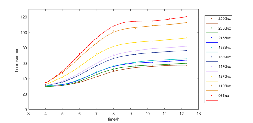
We explored the relationship between fluorescent intensity and illumination intensity, which affects the shade of the color.
Figure 4 shows the red fluorescent intensity of E. coli under light of 620-630nm wavelength with different illumination intensity. We found when illuminated under around 961lux light, we can get the most red fluorescence. We also explore the relationship between green and blue fluorescent intensity of E. coli under light of 515-530nm wavelength and 460-470nm wavelength respectively and illumination intensity. The results are similar, that is, moderate intensity of light is most favorable for E. coli to express fluorescence.
Figure 5 shows results of gel electrophoresis of various parts after PCR with primer VF2\VR. The distance between primer binding sites and both ends of the parts are approximately 150 bp, thus rendering the product about 300 bp longer. The picture is edited to show a more compact photo.
| None |


