Part:BBa_I732005:Experience
This experience page is provided so that any user may enter their experience using this part.
Please enter
how you used this part and how it worked out.
Applications of BBa_I732005
UI Indonesia iGEM team 2013 improve the function of this part by expressing lacZ gene in two separate fragment (BBa_K1182425, the α fragment) and (BBa_K1182000, the ω fragment). These two fragments can interact with each other and still own the enzymatic activity of β galactosidase.
User Reviews
Introduction
For the electrochemical detection system to achieve its full potential, various conditions needed to be optimized for our purposes. These included the buffer solution present and the type of electrode plating used. The final conditions will be incorporated into the field-ready kit that can be used by anyone with minimal training.
Buffer Solutions
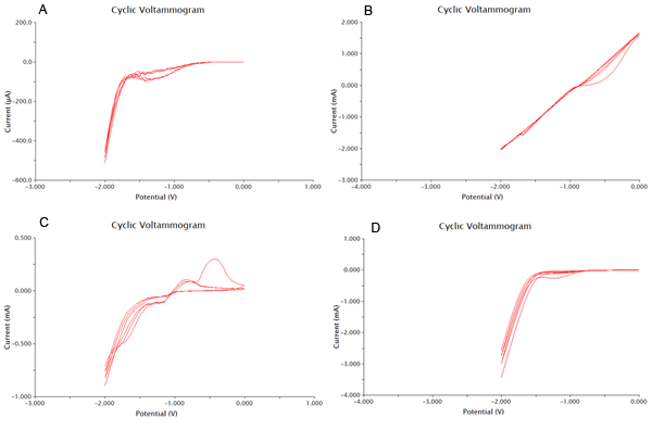
We tested 11 potential buffering systems to find the optimal graph for chlorophenol red detection. The hallmark of a good buffer is one that can conduct a current effectively and has no species present that will undergo a redox reaction at the voltage you are measuring. For our project, we were looking at an oxidation reaction at -0.7V on our detection system. A good buffer for us will have a consistent flat line between -1V and -0.5V. Another feature of a good buffer is that the difference between the cathodic and anodic sweeps is not large. This is easy to notice, as the larger the difference, the bigger the gap between upper and lower lines during the flat section around 0V. The results of our buffer screens are shown in Figure 1 and Figure 2.
Based on the results show above, 0.1M CaCl2 was the best buffering system, as it had consistently flat areas through the testing range and conducted large currents. It was also shown that acetonitrile at 0.01% was the worst solvent, and it caused massive electrode degradation during the test runs.
Plating Methods
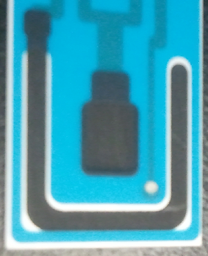
When an electrode is plated with a metal, the metal can participate in redox reactions to release or absorb electrons and conduct a current. This can enhance the resolution of an electrode and produce more easily interpretable results. One important example of plated electrodes is that found for silver/silver chloride electrodes. The silver atoms from the silver chloride can absorb an electron and become silver metal. Due to the nature of this reaction and that it is highly characterized, it can be used as a reference electrode, and is shown as a small silver disk on our electrodes.
We tested a variety of common electroplating metals, including platinum, zinc, nickel, and copper. The results of our tests are shown below in Figure 4. From this data we concluded that nickel plating our electrodes was the best choice, and have included nickel in all of our electrochemistry procedures. This was chosen due to the decrease in size between the cathodic and anodic sweeps, as well as some decreased noise from extraneous species in the buffer. The only other plating method close to NiSO4 was zinc thiocyanate, however this electroplating method had a peak that had higher overlap with the voltage range to be tested.
Detection
Now that we have determined the best buffer and plating methods, we need to start testing our samples. To do this we have used cyclic voltammetry to measure the change in current over a range from -2V to 2V. We performed this sweep 6 times, which would mean that there are 3 cathodic and 3 anodic sweeps. This gives us our data in triplicate. We performed our sweeps at a speed of 100mV/s to increase the amount of data collected and the resoultion of our scans. After this the collected data was processed as shown in the appendix. One extremely important data point we obtained was the number of cells needed to produce optimal results. With more cells the current could be disrupted, and with less cells not enough could be produced.
Results
The final results of our data processing is shown in Figure 1 below. The calculations done to arrive at this final curve are in the appendix.
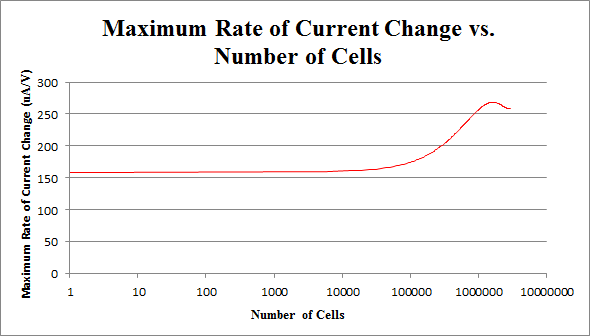
By repeating this procedure for the various tested cell levels, we can construct one of our standard curves - the maximum rate of current change versus number of cells.
We determined the concentration of cells in our culture to be 7.35*108 cells/mL. For the purposes of making a biosensor, we can see that having 105 to 107 cells in our electrochemical system provides a strong signal, while not risking saturating our detection mechanism. This is completely feasible with a small amount of our cell culture.
Appendix
In order to construct our standard curve for current response vs. number of cells, several experiments were conducted with varying numbers of cells, with a constant amount of CPRG (100uL at 0.5M), NaH2PO4 buffer (1mL at 0.5M), and nanopure water (up to 20mL). The cell was left for 5 minutes before the experiment was run.
Figure 2 below shows experimental data for a cyclic voltammetry experiment done with 7.5*105 cells.
We observe the characteristic dip indicative of CPR oxidation at approximately -0.71V, showing the presence of CPR in solution. Next, the time derivative of this curve will be taken, shown below.
Using Figure 3, we determine the maximum rate of change of current to occur at -0.755V, with a maximum of 258.45uA/V.
By repeating this procedure for the various tested cell levels, we can construct one of our standard curves - the maximum rate of current change versus number of cells.
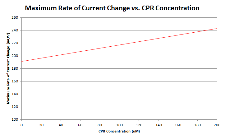
Finally, by varying the amount of CPR in solution, and running cyclic voltammetry experiments in a simple system of only CPR, buffer, and nanopure water, we can construct a standard curve of CPR concentration versus maximum rate of current change. This graph is shown below.
Currently, work is being done to refine our ability to differentiate between varying levels of CPR concentration. Our preliminary data is shown below.
UNIQcc72547ba7222c90-partinfo-0000000B-QINU
|
•••••
Lri |
This part was used as a reporter. It performed as expected. β-gal assays showed that this part was expressed in the expected pattern and was useful as a reporter. |
UNIQcc72547ba7222c90-partinfo-0000000D-QINU

 1 Registry Star


