Part:BBa_I721004
Lead Binding Protein + Promoter (version a)
lead binding protein + promoter (part 11)
Sequence and Features
- 10COMPATIBLE WITH RFC[10]
- 12COMPATIBLE WITH RFC[12]
- 21COMPATIBLE WITH RFC[21]
- 23COMPATIBLE WITH RFC[23]
- 25COMPATIBLE WITH RFC[25]
- 1000INCOMPATIBLE WITH RFC[1000]Illegal SapI.rc site found at 479
Part BBa_1721004 is the Lead Binding Protein + Lead Promoter system
Description
This part is designed to enable Lead Detection in a cell. When Lead (Pb +2) enters the cell, it will couple with the Lead Binding protein, forming a dimer. This dimer will then bind to the Lead Promoter, which is also contained within this part, BBa_I721004. BBa_I721004 contains both the Lead Binding Protein sequence and the Lead Promoter sequence, and should form a standalone Lead Detection system.
This sequence was obtained using PCR from the genome of Ralstonia metallidurans. Biobrick cut sites were added using specific primers during PCR.
This part is not known to function. "PbrR691/promoter combinations in presence of lead nitrate give no GFP production and no AHL production compared to control. "
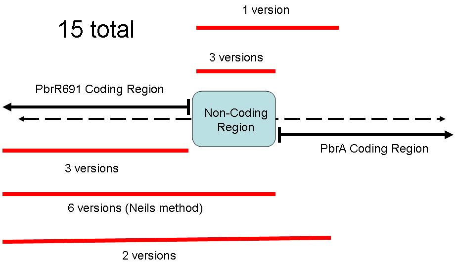
The figure below illustrates the layout of this sequence.
This part contains three sections: A sequence for a Lead Binding Protein, a non-coding region, and a Lead Promoter.
Because of the different coding regions contained in this sequence, the Brown iGEM Team chose 15 different regions of the Pbr691 and PbrR691 sequences to extract. We attempted to create Biobricks from each of these 15 different sequences. Some contained only the PbrR Lead Binding Protein, some contained only the Pbr Promoter, and some parts contained both. The following diagram illustrates these different parts.
BBa_I721004 contains both the Lead Binding Protein region, a non-coding region, and the Lead Promoter region.
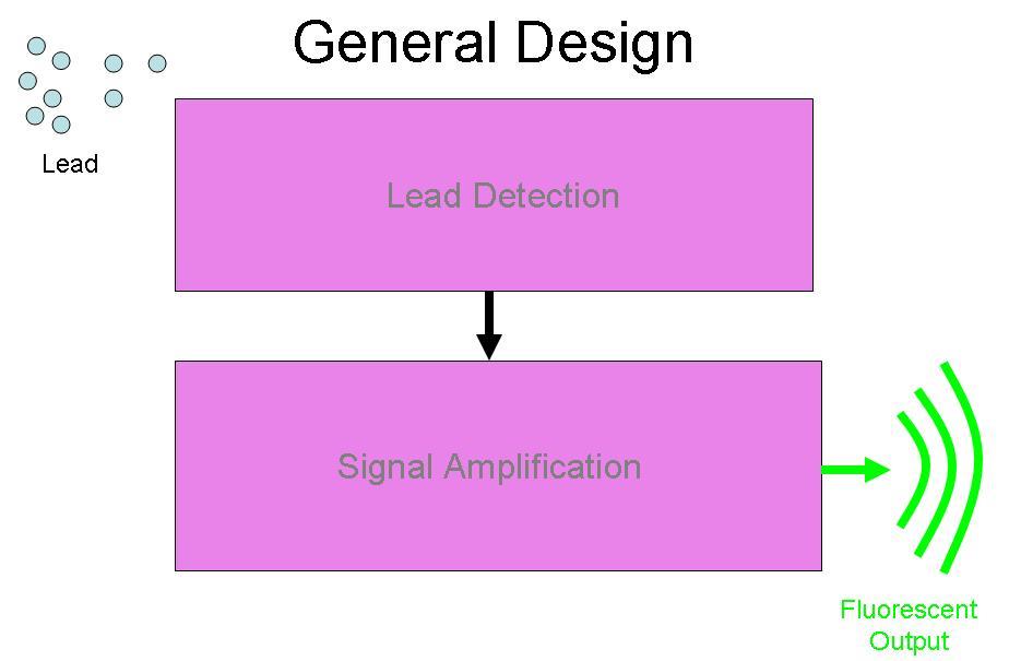
BBa_I721004 was designed to be a part of the Brown University Cellular Lead detector device. The BBa_I721004 Lead Detection system was designed to be attached to the Amplification system by Imperial College, (BBa_J37015), with GFP as the output of the device. The schematic for this project is below:
| None |


