Part:BBa_K546546
The Synchroscillator: A Tunable Synchronized Oscillatory System
This BioBrick device yields an oscillating pattern of Green Fluorescent Protein output, in the way described below. It contains two differing hybrid promoters that allow for stabilization of the oscillation.
Usage and Biology
This system consists of a positive and a negative feedback loop. The positive feedback loop is initiated when the constitutively expressed luxR forms a complex with AHL- which is produced by the protein LuxI. The complex up-regulates the expression of luxI, GFP and AiiA, at first exponentially increasing LuxI, GFP and AiiA levels because the maturation time of LuxI is shorter than that of AiiA. Then the negative feedback loop gets the upper hand: Once maturated, the enzyme AiiA degrades AHL faster than luxI can produce it. Because GFP is under the control of the same promoter as luxI it is highly expressed until AHL is rapidly being degraded by AiiA. Once the AHL concentration is lowered enough, the expression of GFP is halted. At this point the net change in GFP will thus become negative due to the degradation. Since AiiA expression is initiated by the luxR-AHL complex, the production of AiiA also halts which causes the net change of AiiA to become negative and this eventually causes the concentration of AiiA to become low enough to allow a net production of AHL again. Since AHL is a quorum sensing molecule all cells are synchronised in their oscillatory behavior.
Furthermore, this system implements two hybrid promoters: One controlling the transcriptional rate of luxI and the other one controlling the transcriptional rate of AiiA. These two promoters are respectively repressible by IPTG and aTc. Therefore, it should be possible to tune the period and the amplitude of the synchronized oscillations.
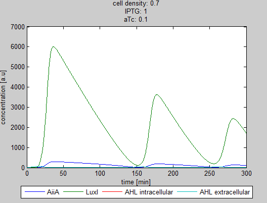
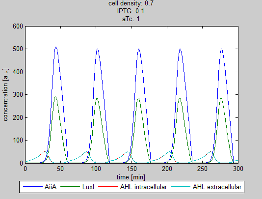
More about this BioBrick device? Another [http://2011.igem.org/Team:Wageningen_UR/Project/IntroductionProj1 description] and the [http://2011.igem.org/Team:Wageningen_UR/Project/ModelingProj1#Mathematical_model_of_the_construct modeling] of are placed on the Wiki page of the project it was made in.
Experimental data
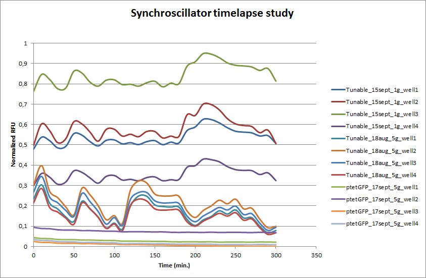
The tunable oscillator was tested in a flow chamber that contained a microdish, designed by Team Wageningen UR 2011. Every 10 min. pictures were taken with an Olympus fluorescence microscope. The setup of the flow chamber is explained [http://2011.igem.org/Team:Wageningen_UR/Project/DevicesSetup here]. After an overnight incubation in the microdish a series of pictures was taken. This was also done for E. coli transformed with ptet-GFP as a fluorescent negative control for oscillation. Four wells from the microdish were clearly visible and those were analyzed using the program [http://rsbweb.nih.gov/ij/ ImageJ]. The outcome is presented in the graph below.
ptet-GFP shows a stable expression over time. This confirms that the differences in fluorescence is not due to fluctuations of the Xenon lamp. ptet-GFP shows a stable expression over time. This confirms that the differences in fluorescence is not due to fluctuations of the Xenon lamp. The Tunable Oscillator was ran on two different dates, each time four wells from the microdish were analyzed with ImageJ. Clearly visible are the large fluctuations in fluorescence. This is the case for both measurement series that were done for the Tunable Oscillator. Especially in the beginning there seems to be an oscillation that looks stable. Both series seem to have the stable periods, and they coincide. After a few hours, however, the oscillation is disrupted and periods are hardly distinguishable.
For an impression of the Synchroscillator in the microdish, see below. For more information about the [http://2011.igem.org/Team:Wageningen_UR/Project/Devices device] and [http://2011.igem.org/Team:Wageningen_UR/Project/CompleteProject1Description circuitry], visit our wiki.
Model
Safety Aspects
A number of safety questions regarding the BioBrick system's [http://2011.igem.org/Team:Wageningen_UR/Safety/One#Risk_Identification_of_BioBrick_System_Inside_the_Cell_Chassis biological safety] and [http://2011.igem.org/Team:Wageningen_UR/Safety/Five biological security] have been answered, you can read specific answers by following the links.
Sequence and Features
- 10COMPATIBLE WITH RFC[10]
- 12INCOMPATIBLE WITH RFC[12]Illegal NheI site found at 7
Illegal NheI site found at 30 - 21INCOMPATIBLE WITH RFC[21]Illegal BglII site found at 2781
- 23COMPATIBLE WITH RFC[23]
- 25INCOMPATIBLE WITH RFC[25]Illegal AgeI site found at 1184
- 1000INCOMPATIBLE WITH RFC[1000]Illegal BsaI.rc site found at 985
Illegal BsaI.rc site found at 2042
Illegal BsaI.rc site found at 2930
Illegal BsaI.rc site found at 3657
| control | (1) J23101 (2) K176000 (3) I751502 (4) R0062 |
| device_type | feedback |
| direction | Forward |
| latency | Seconds |
| protein | (1) LuxR _ (2) AiiA-LVA (3) LuxI-LVA (4) GFP-LVA |
| signalling_molecule | 3OC6HSL (AHL) |
| switch_point | (1) 2nM |


