Part:BBa_K3791021
Efficient gRNA Chloramphenicol construct
This composite part contains an efficient gRNA for CRISPRS-Cas12 use and the necessary elements to allow for the proper transcription of the chloramphenicol efficient gRNA (BBa_K3791016): promoter and terminator. In contrast to the constructs for the transcription of the preliminary gRNAs (not efficient), apart from containing the efficient gRNAs, a terminator was added in order to ensure proper transcription ending. In this way, the gRNA performance improves, thus obtaining better results with this construct when compared to the not efficient (initial) ones.
The promoter used was T7 (BBa_K1614000), which is a strong promoter that allows transcribing a high amount of the gene of interest in a short period of time. When it is used in pertinent competent cells, it is indirectly inducible by the addition of IPTG (as the T7 RNA-polymerase needs IPTG to be expressed) and therefore permits transcriptional modulation. Finally, the terminator chosen was L3S2P21 (BBa_K2675031).
Sequence and Features
- 10COMPATIBLE WITH RFC[10]
- 12COMPATIBLE WITH RFC[12]
- 21INCOMPATIBLE WITH RFC[21]Illegal BglII site found at 81
- 23COMPATIBLE WITH RFC[23]
- 25COMPATIBLE WITH RFC[25]
- 1000COMPATIBLE WITH RFC[1000]
1. Usage and biology: reporter and fluorescence
This part is used inside BL21 competent cells, where we cotransform a plasmid containing the current part, and another containing the LbCas12a (BBa_K2927005) protein. To build our plasmids we used Golden Gate assemby, and to transform them into BL21 cells we used Heat Shock transformation. More details about the building process are available on our Biosensor library building page.
In order to determine if our sensors worked properly we had to first induce our plasmids expression using IPTG (100uM) and then lysate the cells for liberating our CRISPR-Cas construct. The method used for that was enzymatic lysis (using a buffer without EDTA). After lysing our cells we proceed with the detection.
As context we must point out that for our CRISPR-Cas ensemble to be a detection system, what we did was to add a reporter to the media where the Cas may become active. The basis relies on LbCas12aâs special property of collateral trans cleavage activity. That means that when it recognizes the specific target sequence determined by the designed gRNA with which it is coupled (thus becoming active) it unspecifically cuts not only the target DNA but also any dsDNA present in the media. In this way, whenever Cas is activated, fluorescence arises because the reporter is cut and releases the fluorescent molecule. All this is step-by-step indicated in Figure 1.
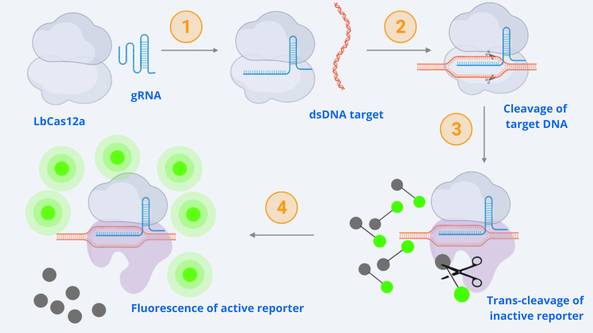
Figure 1 Description: General schematic of Cas12-gRNA-reporter functioning containing the main enzymatic reactions. Cas12 binds to the gRNA, this complex gets activated by recognizing the specific target and cis-cleavage activity starts by cutting this dsDNA target. After that, cas12 trans-cleavage collateral activity cuts any nonspecific DNA fragment, cleaving the reporter. The reporter contains a quencher, which inhibits the fluorophore, and when cutted, luminescence comes out.
2. Characterization: CRISPR-Cas12 enzyme kinetics model
This model was created by ARIA with the aim of understanding the dynamics and limitations of using the CRISPR-Cas technology for detection purposes. For that, experimental data extracted from experiments performed with this efficient gRNA construct coupled with our Cas protein, LbCas12a, was used.
2.1. Model building
As displayed in the schematic diagram in Figure 1, four different steps can be defined in order to model the kinetic dynamics of the system [1]. For our simulation, we will focus on the second part of the process (last two steps), starting from the active Cas-gRNA complex, assuming in this way that the Cas12 and gRNA couple together and get activated by the dsDNA template super fast.
The reaction which represents these two steps is given by Michaelis-Menten kinetics [2]:
Figure 2 Description: Kinetic reaction representing general Michaelis-Menten kinetics. It can be applied to the Cas-gRNA complex and the reporter.
Where E stands for the enzyme (Cas-gRNA complex) that transforms the substrate (S = inactive reporter) into product (P = cleaved reporter). So in our case E is the Cas-gRNA complex, which produces fluorescence by cutting the reporter, representing its conversion from an inactive reporter (S) into an active reporter (P). The intermediate step represented as C simply corresponds to the complex resulting by the binding of Cas-gRNA to the inactive reporter.
The rates of the reaction are: Kf the forward rate constant, Kr the reverse rate constant and Kcat the catalytic rate constant. It is also important to point out the directions of the chemical reactions, which are represented by the arrow's direction. Double direction stands for a reversible process meanwhile the final forward arrow represents the product formation (irreversible) [2].
By contemplating and solving the equations for each of the system components and making several assumptions (see section 2.2 below) and a set of calculations (see more info in the Model page), we obtain a linear ODE representing the product concentration change with time (equation 1):
Equation 1 Description: Differential equation for final product dynamics over time applying the assumptions and parameter definitions exposed above.
By defining Ï = KM/KcatE0 and solving analytically the differential equation for the concentration of product formed (cleaved reporter) over time, we obtain the result in equation 2:
Equation 2 Description: Equation for final product dynamics over time after defining parameter Ï and solving analytically the differential equation.
2.2. Assumptions summary and parameters
In this section, we present a little summary of all the assumptions made during the model design. It is extremely important to take into account all the assumptions when analyzing the results of the model, and to iterate in the process until finding the appropriate level of simplification which allows reality representation in an easy way without losing system important dynamics. After our iterative engineering process, the final model assumptions are:
- Cas12 and gRNA couple together and get activated by the dsDNA template super fast
- Degradation rates can be neglected, assuming them <<1
- Quasi equilibrium assumption: Cas12-gRNA complex cleaves the reporter fast compared to the cutting time
- E0 is assumed to be the concentration of dsDNA template used in each experiment, since usually the Cas-gRNA complex is present in abundance [1]
- Substrate concentration is much smaller than the Michaelis-Menten constant: [S] <<KM [1]
In order to perform model simulations, we need to know which are the values for the variables in equation 2. That means we must find the proper values for KM, Kcat, S0 and E0. The two first ones are established rates that were extracted from the literature and can be seen in the table below, whereas S0 and E0 depend on experimental specifications.
| Parameter | Value | Source |
| KM LbCas12a | 7.25 x 10⁻⁷ M | [1] |
| Kcat LbCas12a | 1250 s-1 | [2] |
On the one hand, we must find the inactive reporter concentration (S0), which is the same for all the detection tests. This was done through a set of calculations:
- IDT reporter contains 2 nmol per bulk tube
- We diluted it in 1mL of nuclease-free water, thus obtaining 2 nmol/mL
- In each reaction, 5uL in a total volume of 50uL were used. Using these data, we can calculate the final reporter concentration: 200nM
Calculations Description: Conversion factor through which the used reporter concentration in Molar can be calculated from the commercial kit reporter concentration.
2.3. Model validation with BBa_K3791021 experimental data
On the other hand, after having computed the reporter concentration (S0), we then need to calculate the dsDNA template concentration (E0) at play. On the contrary to S0, this concentration depends on the specific reaction we carry out, as we perform many of them when aiming to detect different samples. In this specific case, we desire to detect a specific Chloramphenicol resistant gene region, defined by the gRNA described in this part. For doing the specific calculations, we took the following experimental information into account:
- The concentration of the sample containing the plasmid with the target gene concentration was normalized to 90ng/μL
- As we used 4μL per reaction in a total volume of 50μL, the mass concentration used was:
Calculations Description: Conversion factor through which the used dsDNA template mass concentration can be calculated from the stock dsDNA template concentration.
The next step was to convert this concentration to molar. For this, we use NEBioCalculator [3] introducing the target DNA sequence (the plasmid containing the Chloramphenicol resistance gene aiming to be detected) as well as the mass concentration to obtain 1.744 fmol/μL as molar concentration. Finally, this was converted to mol/L to obtain a template molar concentration of: 1.744 x 10⁻⁹ M.
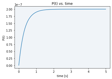
Finally, using the final model solved equation (2), we performed simulations obtaining the following plot in Figure 3, which shows us the model dynamics with the rates in Table 1 and obtained parameters from the previous calculations.
Figure 3 Description: Simulation result plot showing the final product dynamics over time. It is the typical Michaelis-Menten curve which gets saturated extremely fast (in approx. 3 seconds) to the total product concentration.
As it can be seen in the plot above, all the initial substrate gets very fastly transformed into the final product, in just a matter of barely three seconds. The maximum final product concentration value shown in the graph is S0, meaning that it is defined by the initial amount of inactive reporter since all of it is converted into active reporter (product).
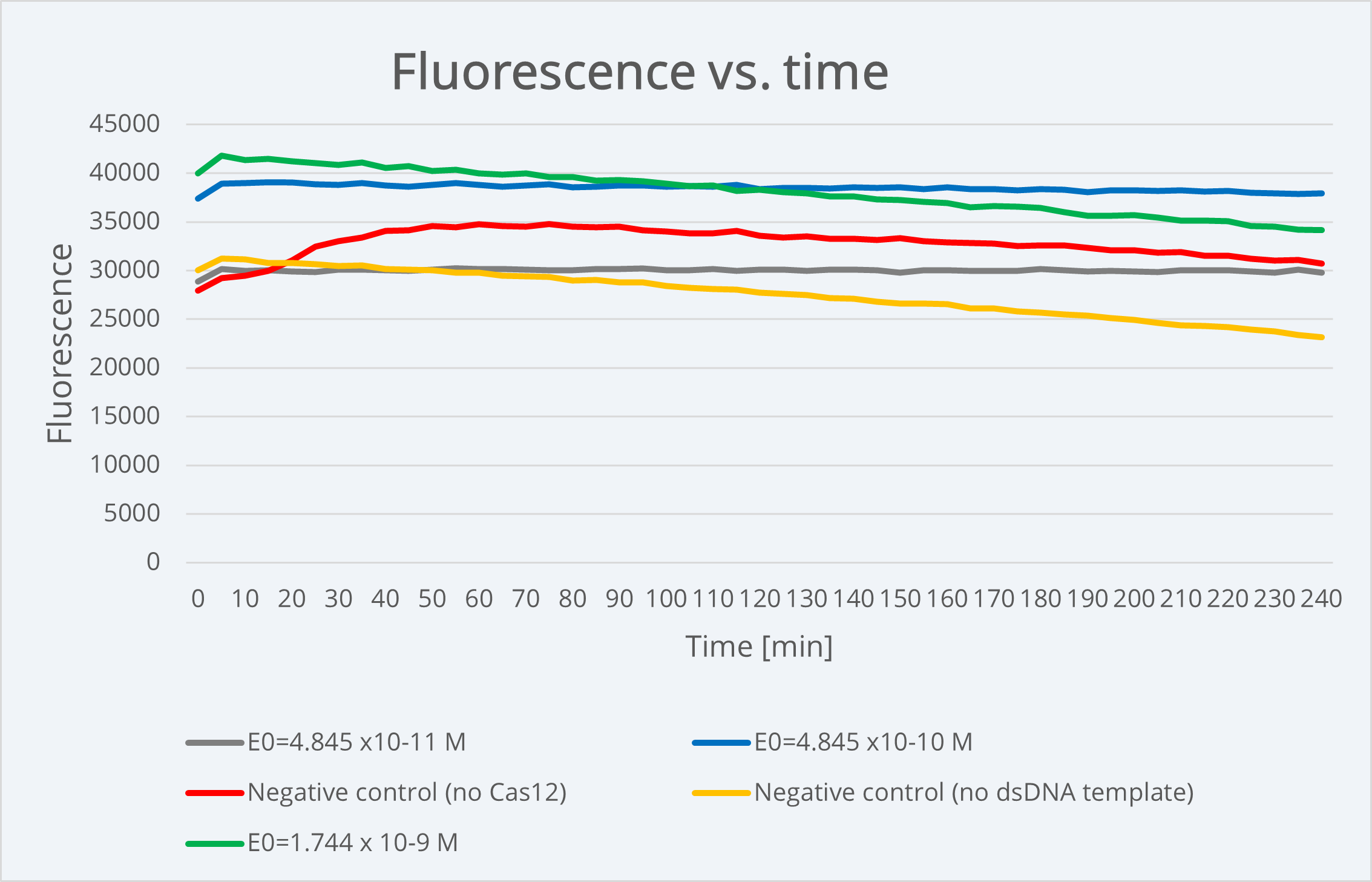
When comparing our simulation plot with our experimental results using BBa K3791021 (see green line in Figure 3), where we generally see high and constant fluorescence values, it makes sense. We did this by considering that the final product concentration is proportional to the amount of fluorescence, since, as we know and was already explained above, the active reporter leads to fluorescence.
Figure 4 Description: Experimental results plot showing fluorescence dynamics over 240min of time with different dsDNA target concentrations as well as positive and negative controls dynamics e. The fluorescence is approximately stable over time, meaning that experimentally we are not able to see the typical Michaelis-Menten curve because it happens before starting the measurement.
For technical restrictions, we started measuring the fluorescence long after the reaction happens (in the scale of minutes), so the experimental values we obtained correspond to the graph part where the fluorescence is plateaued at its maximum value. As the reaction happens and stabilizes almost instantaneously due to its intrinsic nature, using these parameters, it is physically impossible to be able to see experimentally the complete Michaelis-Menten curve in order to obtain data about the reporter activation event.
With the aim of being capable of analyzing the course of the reaction, we studied different options of varying our model parameters that could be useful for our purpose. Among the possible parameters to change the reaction speed state above, E0 is the most controllable, since it corresponds to the dsDNA template concentration, that is, the concentration of the Chloramphenicol resistant plasmid used as target sample. We tried to replicate our experiments using a lower E0 concentration, but when we did the measurements the fluorescence was already plateaued. More details about this can be consulted in our Model page.
3. Characterization: Experimental results
3.1. Testing conditions
The fluorescence emitted by our system cannot be seen by naked eye, it needs to be checked with special light. Moreover, if we desire not only to determine its presence but also quantify it, we use special machinery as a Plate Reader. In our case, quantifying the amount of fluorescence resulting from our reactions was especially important as since we performed the detections in lysed bacterial cells there were lots of DNases, apart from Cas, cutting the reporter. The specifications for the configuration of the Plate Reader which are specified in Table 1 were designed by us, adapting the wavelength values to the ones specified in the reporter user manual. More details about measurement conditions are available in our Results measurement page.
| Parameters | Value |
| Temperature | 37ºC / Room temperature |
| Duration | 2h |
| Use kinetic interval | Measure every 5 minutes |
| Excitation | 530 nm |
| Emission | 560 nm |
| Number of flashes | 20 |
| Measure from | Bottom |
| Gain | Optimal (100 RFA) + Use Gain Regulation |
3.2. Best detection results
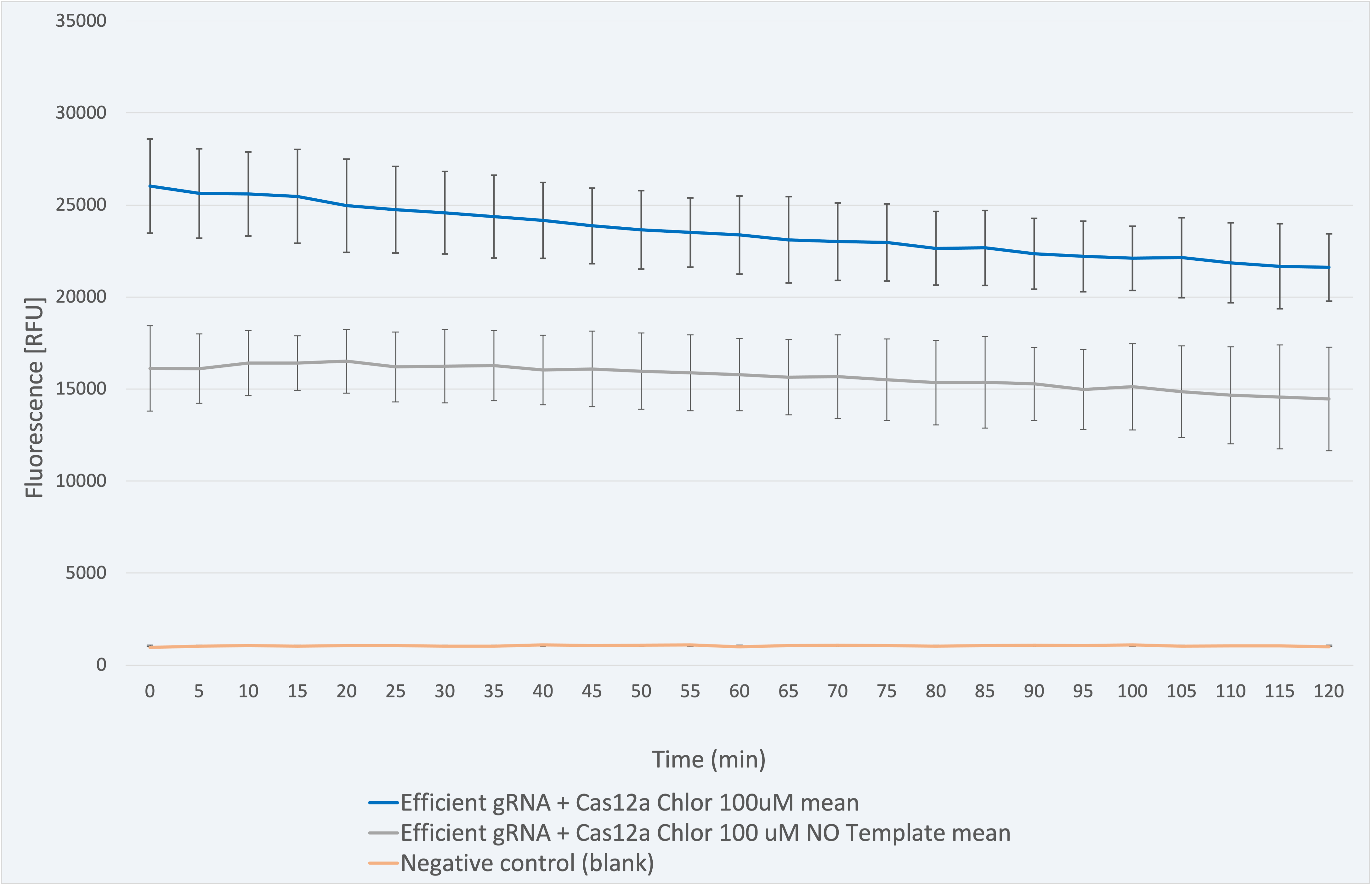
All experiments have been conducted under controlled conditions to respect procedural consistency and thus achieve the highest reproducibility of the results. For the results shown below, three biological replicates were used to ensure trustability.
The fluorescence results for this composite part + LbCas12a (BBa_K2927005) in Figure 5 range between 26031 and 21607 RFU and are coherent since the one with sample needs to be higher due to the gRNA - sample sequence match. The decrease in fluorescence signal is only 16.99% over 2 -hour time, which indicates a maintained stability of the signal.
Figure 5 Description: This figure shows a graphic of the fluorescence measurements for gRNA for Chloramphenicol resistant gene+Cas12a, a negative control (without sample) and a blank.
The biological significant negative control (without sample) produces a signal which is 38.1% lower in RFU than the one given by the biosensor with its corresponding sample. It ranges between 16118 and 14461 RFU. This is attributed to the nuclease activity released from the lysis process. In both cases, the fluorescence is much higher than in the blank (negative control with water), a fact that is consistent.
Therefore, the results confirm our engineered biological system serves as a biosensor and accomplish the purpose for which it was created.
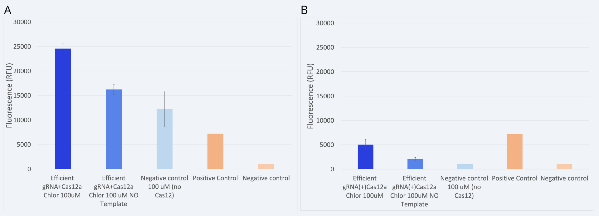
The previous graph was obtained by testing the approach where we cotransform our two plasmids containing the gRNA construct and the Cas12 protein in the same cell (âjointâ approach). This procedure aimed to ensure the biosensors assembly prior to the addition of the target DNA.
However, another constraint was tested. In this case, Cas12a and gRNA plasmids were transformed and expressed in bacteria separately (âseparateâ approach). Then, when preparing the detection reaction, both components were mixed in situ. This approach allowed us to test how long would it take for the Cas12a to couple with the gRNA, and consequently digest the target DNA sequence. Results comparing both approaches are shown in Figure 6.
While in the âjointâ approach a clear detection is observed, in the case of the âseparateâ approach the results obtained are not reliable. More replicates and further experiments are needed to confirm under which conditions could we perform the âseparateâ approach and obtain reliable and coherent results. It is hypothesized that the necessary conditions for Cas12a and gRNA coupling have not been met. In order to carry out this approach, a better protocol sequence should be studied.
References
[1] Ramachandran, A., and Santiago, J. G. (2021). Enzyme kinetics of CRISPR molecular diagnostics. Biorxiv. doi: 10.1101/2021.02.03.429513
[2] Chen, W. W., Niepel, M., and Sorger, P. K. (2010). Classic and contemporary approaches to modeling biochemical reactions. Genes and Development, 24(17), 1861â1875. doi: 10.1101/gad.1945410
[3] NEBioCalculator. (2021). NEBioCalculator. NEBioCalculator
//function/crispr/grna/construct
//function/crispr/grna/efficient
| None |


