Difference between revisions of "Part:BBa K864401"
Tesswiglund (Talk | contribs) |
Tesswiglund (Talk | contribs) |
||
| Line 220: | Line 220: | ||
While running a nanoDSF measurement the aggregation can also be monitored. This data results in an aggregation onset, which corresponds to the temperature where the protein starts to aggregate, as well as the midpoint of aggregation (TAm-value) where 50% of the protein is aggregated. The temperature for aggregation onset and midpoint of aggregation for the different samples were summarized in table 1 and graphs were constructed by plotting one of several replicates and is representative for all samples. The temperature for aggregation onset is visualized by the point where the curve starts to slope uphill in figure 7 and 8 and the TAm-value is represented by the midpoint of the slope in figure 7 and by the midpoint of the peak in figure 8. As best visualized in table 1, the aggregation onset for free aeBlue is slightly higher from the aggregation onset for aeBlue encapsulated in liposomes, and aeBlue outside of liposomes. Furthermore, it can be seen in table 1 that there is a downward trend for the aggregation onset temperature with increasing concentration of liposomes. However, the aggregation midpoint is similar between the samples at around 78.4 ºC, suggesting that the protein aggregation is not affected by encapsulation in liposomes or the presence of liposomes. Furthermore, it can be seen by the baseline of the scattering curves in figure 7 that a higher concentration of liposomes results in a higher base level of scattering, further proving that there are liposomes present. | While running a nanoDSF measurement the aggregation can also be monitored. This data results in an aggregation onset, which corresponds to the temperature where the protein starts to aggregate, as well as the midpoint of aggregation (TAm-value) where 50% of the protein is aggregated. The temperature for aggregation onset and midpoint of aggregation for the different samples were summarized in table 1 and graphs were constructed by plotting one of several replicates and is representative for all samples. The temperature for aggregation onset is visualized by the point where the curve starts to slope uphill in figure 7 and 8 and the TAm-value is represented by the midpoint of the slope in figure 7 and by the midpoint of the peak in figure 8. As best visualized in table 1, the aggregation onset for free aeBlue is slightly higher from the aggregation onset for aeBlue encapsulated in liposomes, and aeBlue outside of liposomes. Furthermore, it can be seen in table 1 that there is a downward trend for the aggregation onset temperature with increasing concentration of liposomes. However, the aggregation midpoint is similar between the samples at around 78.4 ºC, suggesting that the protein aggregation is not affected by encapsulation in liposomes or the presence of liposomes. Furthermore, it can be seen by the baseline of the scattering curves in figure 7 that a higher concentration of liposomes results in a higher base level of scattering, further proving that there are liposomes present. | ||
| − | + | {{#tag:html| | |
| + | <div style="display : flex; align-items: flex-start; flex-direction : row;"> | ||
| + | <div style="margin :10px;"> | ||
| + | <img src="https://static.igem.wiki/teams/5387/bba-k864401-aggregation-analysis-graph-1.png" width="400px"/> | ||
| + | <p style="font-size : 11px">Figure 8. Representative scattering curve of aeBlue, aeBlue encapsulated in liposomes and aeBlue in the presence of liposomes. Temperature is on the X-axis and the scattering is on the Y-axis. The midpoint of the slopes suggests a TAm-value around 78.4 ºC for all samples and where the curves start to slope uphill represents the aggregation onset temperatures.</p> | ||
| + | </div> | ||
| + | <div style="margin : 10px;"> | ||
| + | <img src="https://static.igem.wiki/teams/5387/bba-k864401-aggregation-analysis-graph-2.png" width="400px"/> | ||
| + | <p style="font-size : 11px">Figure 9. Representative scattering curve of aeBlue, aeBlue encapsulated in liposomes and aeBlue in the presence of liposomes. Temperature is on the X-axis and 1st derivative of scattering is on the Y-axis. The midpoint of the peaks suggests a TAm-value around 78.4 °C for all samples and where the curves start to slope uphill represents the aggregation onset temperatures.</p> | ||
| + | </div> | ||
| + | </div> | ||
| + | }} | ||
<span class='h3bb'><strong>Table 1. Summary of data from the nanoDSF measurements</strong></span> | <span class='h3bb'><strong>Table 1. Summary of data from the nanoDSF measurements</strong></span> | ||
| Line 270: | Line 281: | ||
===References=== | ===References=== | ||
| − | [1] | + | [1] NanoDSF - NanoTemper Technologies. NanoTemper Technologies. 2024. Available from: https://nanotempertech.com/nanodsf/ |
<br> | <br> | ||
| − | [2] | + | [2] Deegan, R., Bakajin, O., Dupont, T. et al. Capillary flow as the cause of ring stains from dried liquid drops. Nature 389, 827–829 (1997). https://doi.org/10.1038/39827 |
<br> | <br> | ||
| − | [3] | + | [3] Li, Y., Forbrich, A., Wu, J. et al. Engineering Dark Chromoprotein Reporters for Photoacoustic Microscopy and FRET Imaging. Sci Rep 6, 22129 (2016). https://doi.org/10.1038/srep22129 |
<br> | <br> | ||
| − | [4 | + | [4] NanoTemper Technologies. (n.d.). Why are there unfolding profiles in different directions? Retrieved from support.nanotempertech: https://support.nanotempertech.com/hc/en-us/articles/19208573958801-Why-are-there-unfolding-profiles-in-different-directions |
| − | + | ||
| − | + | ||
| − | + | ||
| − | + | ||
Revision as of 21:28, 28 September 2024
aeBlue blue chromoprotein
aeBlue is a blue chromoprotein extracted from the basal disk of a beadlet anemone Actinia equina. The protein has an absorption maximum at 597nm and a deep blue colour. The protein aeBlue has significant sequence homologies with proteins in the GFP family.
Important: This part is not available in the registry yet, however, the same part is available from the registry with the standard RBS B0034: BBa_K1033929.
Source
The protein was first extracted and characterized by Shkrob et. al. 2005 under the name aeCP597. This version is codon optimized for E coli by Bioneer Corp.
Below to the left is the expressed aeBlue in E coli. To the right comparison of aeBlue with other chromoproteins available from the registry.
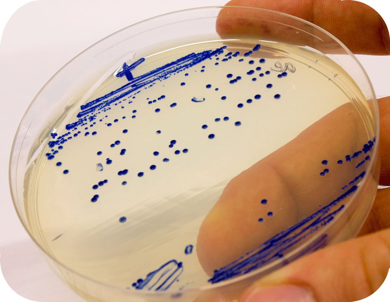
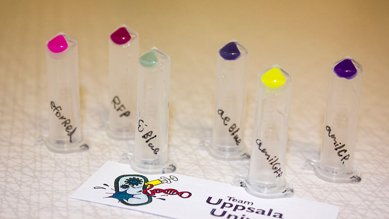
iGEM12_Uppsala_University: Left picture: Visual color expression of aeBlue(BBa_K864401).
Right picture: The Uppsala chromoprotein collection and RFP. Pellets of bacteria expressing chromoproteins eforRed (BBa_K592012), RFP (BBa_E1010), cjBlue (BBa_K592011), aeBlue (BBa_K864401), amilGFP (BBa_K592010) and amilCP (BBa_K592009).
Characterization
NJTech_China 2021’s Characterisation
Group: NJTech_China iGEM 2021
While most of our project was focused on Design and Construction of Synthetic Yeast-Microalgae Consortia for Biosynthesis of Phenylethanol, we were also interested in chromoproteins. Specifically, we characterized the expression of aeBlue and gfasPurple.
The aeBlue sequence (Part:BBa_K864401) optimized for E. coli was incorporated into plasmid pET-29a(+), transformed into E. coli BL21 for characterization and measurement. We provided aeBlue with results and data based on protein expression and purification, TOF-Mass spectrometry, full wavelength measurement and Swiss-model.
Methods:
SDS-PAGE, TOF-Mass Spectrometry, BCA (Bicinchoninic acid) method, full wavelength measurement and Swiss-Model.
Results
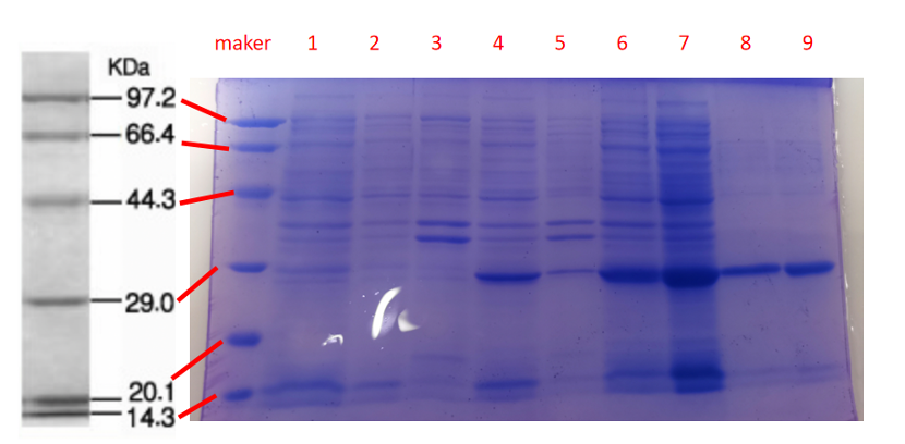
Conclusion: The cell pellet was collected by harvesting 50mL culture after 24h of induction followed by centrifugation at 4 degrees and 6000 rpm for 10min. Then, we performed ultrasonic disruption and collected the supernatant after centrifugation. The protein was purified and collected through ultrafiltration and affinity chromatography.
1· aeBlue- The culture after IPTG induction.
2· aeBlue- The pellet after IPTG induction and ultrasound.
3· aeBlue- Supernatant after IPTG induction and sonication.
4· aeBlue- The culture without IPTG induction.
5· aeBlue- The pellet without IPTG induction after ultrasound.
6· aeBlue- Supernatant sample without IPTG induction after sonication.
7· aeBlue- Protein sample after the ultrafiltration (diluted 20 times).
8· aeBlue- Purified protein sample.
Conclusion: The protein gel preliminarily proved that the molecular mass of the aeBlue protein was correct, which is consistent with the expected molecular mass of aeBlue protein (the molecular mass of aeBlue protein is about 27.3 kDa). Compared with lane 1, 2 and 3, lane 4, 5, and 6 indicate that more aeBlue protein can be obtained with IPTG induction. As is shown in lane 7, the concentration of protein was increased after ultrafiltration concentration. Lane 8 shows that the purification effect of protein after nickel affinity chromatography was better, and the impurity protein was less than before affinity chromatography. In conclusion, it can be seen that our expression and purification strategy is effective.
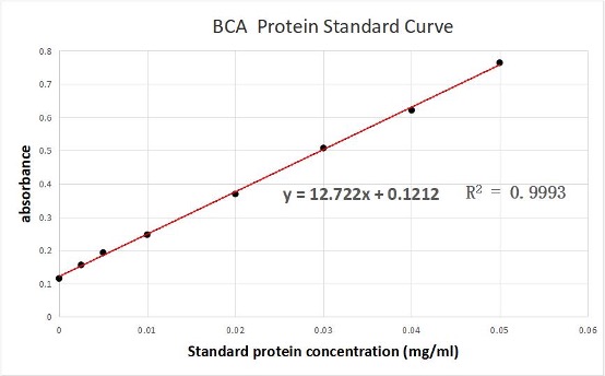
We used the BCA (Bicinchoninic acid) method to measure the concentration of aeBlue protein.
The concentration of aeblue chromoprotein was 9.10 mg/ml.
The standard protein curve fitting equation (R2=0.9993) :
y=12.722x+0.1212
It comes out that:
The concentration of aeBlue is 9.10 mg/ml.
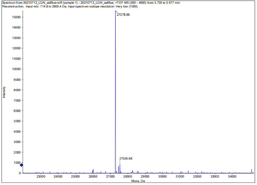
Conclusion : We performed Time of Flight Mass Spectrometer on the purified HIS-tagged aeBlue protein. The predicted molecular mass of this protein is about 27300Da. The result of TOF-Mass Spectrometry showed that the specific molecular mass of aeBlue protein is 27.279kDa (the value of the sharpest peak is shown as the molecular mass of aeBlue protein). Moreover, the intensity of 27.279kDa is up to 1.5×10^5, which indicates the high concentration and purity of the aeBlue protein. There are also some small protein peaks, suggesting that the noise had some effect, but not much.
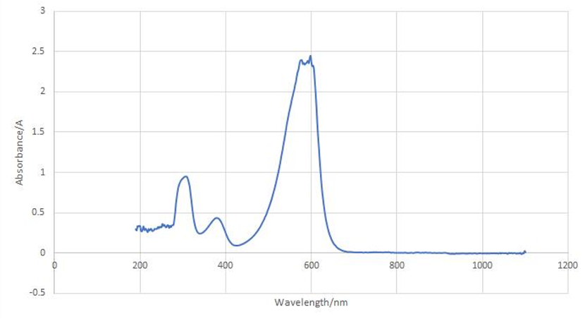
aeBlue protein full-wavelength scan profile :
1-204nm 0.282A
2-598nm 2.446A
3-272nm 0.322A
4-1040nm 0.003A
Conclusion : The full-wavelength scan of aeBlue protein shows that the strongest absorption peak of aeBlue protein occurs at 598nm. As shown in the results, aeBlue has a low intensity peak at 204 to 272 nm, which may be due to the fluorescence excitation.
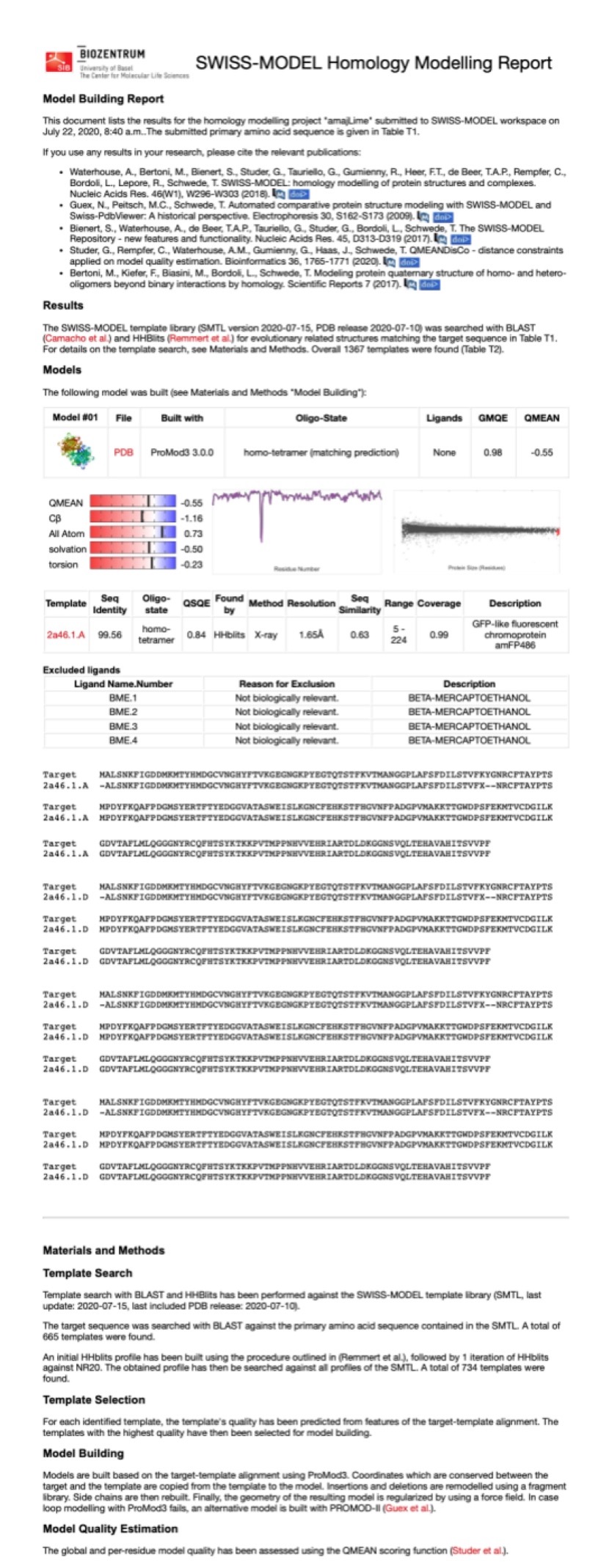
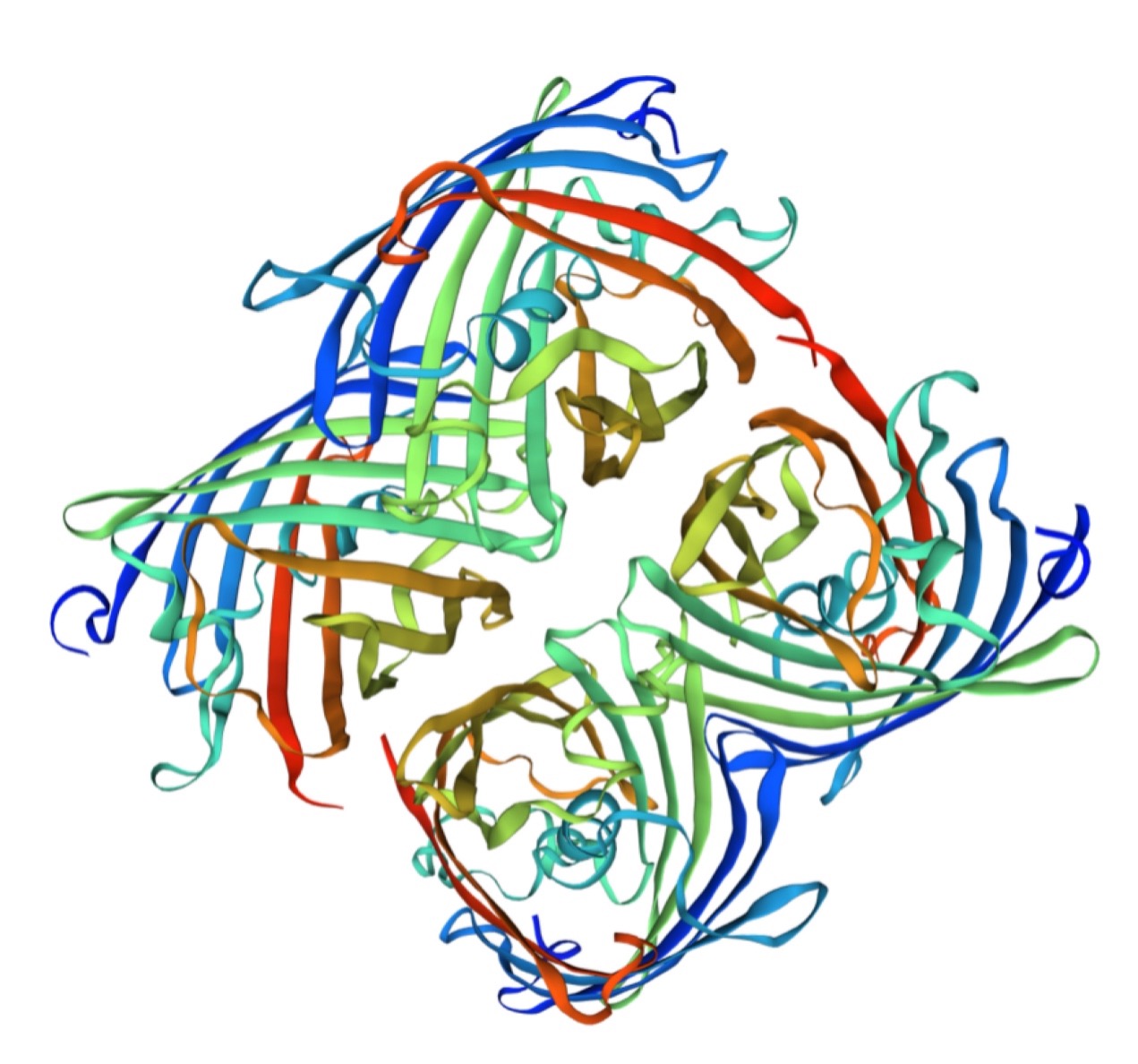
Structural modeling results of the aeBlue protein based on Swiss-Model
Conclusion: We used Swiss-Model to simulate the three-dimensional structure of aeBlue protein. The above figures showed the modeling result of Swiss-Model.
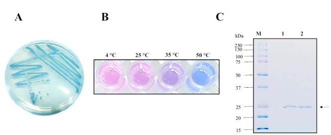
The color change of aeBlue depend on temperature
(Supplement by NWU-CHINA-A 2021)
According to the work done by Tamayo-Nuñez J et al in recent years, aeBlue shows a color change depending on temperature.[1] When the temperature decreased to 4 degree centigrade, the color of purified aeBlue solution changed to pink. And it’s color would recover to blue at a higher temperature.
References
[http://www.ncbi.nlm.nih.gov/pmc/articles/PMC1316306/]Shkrob, M.A., Yanushevich, Y.G., Chudakov, D.M., Gurskaya, N.G., Labas, Y.A., Poponov, S.Y., Mudrik, N.N., Lukyanov, S., Lukyanov, K.A., 2005. Far-red fluorescent proteins evolved from a blue chromoprotein from Actinia equina. Biochem. J. 392, 649–654.
[1]Tamayo-Nuñez J, de la Mora J, Padilla-Vaca F, et al. aeBlue Chromoprotein Color is Temperature Dependent. Protein and Peptide Letters. 2020 ;27(1):74-84. DOI: 10.2174/0929866526666190806145740. PMID: 31385759; PMCID: PMC6978647.
Encapsulation in liposomes, Thermal unfolding and Aggregation analysis
Group: Linköping iGEM 2024
Authors: Tess Wiglund, Moa Ackemark, Isac Kreku
Summary: We encapsulated aeBlue into liposomes, as our project aims to encapsulate different proteins. We then separated the encapsulated aeBlue from the free aeBlue with a size exclusion chromatography (SEC). To validate successful encapsulation we visualized the liposomes in a microscope. Using prometheus we performed a Differential Scanning Fluorimetry (nanoDSF) measurement on aeBlue to acquire the Tm -value, as well as analyze the aggregation through light scattering.
Methods: We chose to order aeBlue as a linear sequence, based on the sequence in the airtable. We then ligated it into pET-28 a (+) before transforming into NEB-5-alpha competent cells and later on BL21 E. coli cells. After that we purified the protein using a PD 10 nickel column. At the end we had our aeBlue in PBS buffer. From there we encapsulated different concentrations of aeBlue into liposomes with a diameter of 200 nm using thin film hydration and extrusion. We used the concentrations 0,1 mg/ml, 0,5 mg/ml and 2 mg/ml based on literary studies [1-2].
We then separated the liposomes containing aeBlue from the free aeBlue using SEC as a method. After that we visualized them in a microscope. Samples were prepared with liposomes stained with the dye Nile red as it fluoresces in lipid rich environments. All samples were prepared on superfrost glass slides by applying 3µl of sample left to dry, which were thereafter rewetted by application of fluorescence mounting medium.
Nano-DSF uses intrinsic fluorescence to measure the change in fluorescence intensity over an increasing temperature to obtain the Tm-value, where 50% of the protein is unfolded. aeBlue contains 2 tryptophans (Trp) and 9 tyrosines (Tyr), which are both important for nano-DSF measurements. Both Trp residues and Tyr are on the inside of the protein and get exposed when it unfolds, which changes the fluorescence [3].
Results: The results from microscopy suggest that we successfully encapsulated aeBlue, however further studies would be necessary to validate encapsulation. The nano-DSF gave a Tm-value of 79.5 ± 0.1 °C for aeBlue alone and showed that the protein started to aggregate at 69.3 ± 0.7 °C. The results from the prometheus are summarized in Table 1. The results from the nano-DSF further strengthen successful encapsulation.
Size exclusion and microscopy analysis
To separate the liposomes from surrounding aeBlue, a size exclusion chromatography was performed. Microscopy was then used to prove the presence of protein in liposomes. Samples were prepared with liposomes stained with the dye Nile red as it fluoresces in lipid rich environments. All samples were prepared on superfrost glass slides by applying 3µl of sample left to dry, which were thereafter rewetted by application of fluorescence mounting medium. The area of importance is highlighted with white or black dotted lines. This procedure renders a “coffee ring” effect where liposomes and proteins are collected as a ring following the drying droplet [4].
The area of importance is highlighted with white or black dotted lines. As seen in figure 2 there are clusters of dots which we previously showed differed from the sample with only aeBlue (figure 1). These findings in combination with the high fluorescence of Nile red, the conclusion can be drawn that there are lipid structures in the sample suggesting that liposomes are present after size exclusion chromatography. Furthermore, it can be seen in figure 3 and figure 4 that there are clusters of small dots present. This suggests that aeBlue is present in the same sample as liposomes after the size exclusion chromatography, which would mean the encapsulation was successful.

Figure 1. 2 mg/ml aeBlue outside of liposomes, in bright field.

Figure 2. 2 mg/ml aeBlue encapsulated in liposomes, in bright field.

Figure 3. 2 mg/ml aeBlue encapsulated in liposomes after SEC, in fluorescent light with excitation at 535 nm.

Figure 4. 2 mg/ml aeBlue encapsulated in liposomes after size exclusion chromatography, in bright-field microscopy.

Figure 5. The SEC column after washing the column with 500 ml PBS after applying aeBlue. The blue color of the column indicates that it has affinity for aeBlue.
Thermal unfolding
To study the thermal unfolding of the chromoprotein aeBlue in presence of liposomes, a nanoDSF measurement was performed. The Trp fluorescence in aeBlue is quenched in the folded structure, probably due to the phenomenon fluorescence resonance energy transfer (FRET) to the chromophore [5]. Therefore the intrinsic fluorescence was plotted at 350 nm, corresponding to the unfolded structure of the chromoprotein, because the Trp fluorescence increased during unfolding [6] (figure 5). The temperature interval was set to 20 ºC - 110 ºC with an increasing temperature of 1.0 ºC/ min. The midpoint of thermal denaturation (Tm-value) is represented by the middle of the slope in figure 5 and by the midpoint of the peak in figure 6. The different Tm-values for the samples can be seen in table 1. It can be seen in figure 5, 6 and table 1 that the thermal stability of free aeBlue, aeBlue inside liposomes and aeBlue outside of liposomes is similar since the Tm-value for the different samples are all around 79.5 ºC. This suggests that the thermal stability of aeBlue is not affected by encapsulation in liposomes or the presence of liposomes.

Figure 6. Representative unfolding curve of aeBlue, aeBlue encapsulated in liposomes and aeBlue in the presence of liposomes. Temperature is on the X-axis and the fluorescence intensity at 350 nm on the Y-axis. The midpoint of the slopes suggests a Tm-value around 79.5 ºC for all samples.

Figure 7. Representative unfolding curve of aeBlue, aeBlue encapsulated in liposomes and aeBlue in the presence of liposomes. Temperature is on the X-axis and 1st derivative at 350 nm on the Y-axis. The midpoint of the peaks suggests a Tm-value around 79.5 ºC for all samples.
Aggregation analysis
While running a nanoDSF measurement the aggregation can also be monitored. This data results in an aggregation onset, which corresponds to the temperature where the protein starts to aggregate, as well as the midpoint of aggregation (TAm-value) where 50% of the protein is aggregated. The temperature for aggregation onset and midpoint of aggregation for the different samples were summarized in table 1 and graphs were constructed by plotting one of several replicates and is representative for all samples. The temperature for aggregation onset is visualized by the point where the curve starts to slope uphill in figure 7 and 8 and the TAm-value is represented by the midpoint of the slope in figure 7 and by the midpoint of the peak in figure 8. As best visualized in table 1, the aggregation onset for free aeBlue is slightly higher from the aggregation onset for aeBlue encapsulated in liposomes, and aeBlue outside of liposomes. Furthermore, it can be seen in table 1 that there is a downward trend for the aggregation onset temperature with increasing concentration of liposomes. However, the aggregation midpoint is similar between the samples at around 78.4 ºC, suggesting that the protein aggregation is not affected by encapsulation in liposomes or the presence of liposomes. Furthermore, it can be seen by the baseline of the scattering curves in figure 7 that a higher concentration of liposomes results in a higher base level of scattering, further proving that there are liposomes present.

Figure 8. Representative scattering curve of aeBlue, aeBlue encapsulated in liposomes and aeBlue in the presence of liposomes. Temperature is on the X-axis and the scattering is on the Y-axis. The midpoint of the slopes suggests a TAm-value around 78.4 ºC for all samples and where the curves start to slope uphill represents the aggregation onset temperatures.

Figure 9. Representative scattering curve of aeBlue, aeBlue encapsulated in liposomes and aeBlue in the presence of liposomes. Temperature is on the X-axis and 1st derivative of scattering is on the Y-axis. The midpoint of the peaks suggests a TAm-value around 78.4 °C for all samples and where the curves start to slope uphill represents the aggregation onset temperatures.
Table 1. Summary of data from the nanoDSF measurements
| n | Tm (350 nm) (°C) | Aggregation onset (°C) | TAm aggregation midpoint (°C) | |
|---|---|---|---|---|
| aeBlue 0.5 mg/ml | 10 | 79.5 ± 0.1 | 69.3 ± 0.7 | 78.4 ± 0.1 |
| 1.8 mM liposomes with 1.9 mg/ml aeBlue inside and 0.5 mg/ml aeBlue outside | 3 | 79.2 ± 0.1 | 68.4 ± 0.2 | 78.3 ± 0.1 |
| 3.6 mM liposomes with 0.5 mg/ml aeBlue outside | 3 | 79.5 ± 0.1 | 67.3 ± 0.6 | 78.4 ± 0.1 |
| 1.8 mM liposomes with 0.5 mg/ml aeBlue outside | 3 | 79.6 ± 0.1 | 67.5 ± 0.5 | 78.3 ± 0.04 |
| 0.9 mM liposomes with 0.5 mg/ml aeBlue outside | 3 | 79.6 ± 0.1 | 68.1 ± 0.7 | 78.4 ± 0.03 |
References
[1] NanoDSF - NanoTemper Technologies. NanoTemper Technologies. 2024. Available from: https://nanotempertech.com/nanodsf/
[2] Deegan, R., Bakajin, O., Dupont, T. et al. Capillary flow as the cause of ring stains from dried liquid drops. Nature 389, 827–829 (1997). https://doi.org/10.1038/39827
[3] Li, Y., Forbrich, A., Wu, J. et al. Engineering Dark Chromoprotein Reporters for Photoacoustic Microscopy and FRET Imaging. Sci Rep 6, 22129 (2016). https://doi.org/10.1038/srep22129
[4] NanoTemper Technologies. (n.d.). Why are there unfolding profiles in different directions? Retrieved from support.nanotempertech: https://support.nanotempertech.com/hc/en-us/articles/19208573958801-Why-are-there-unfolding-profiles-in-different-directions
Sequence and Features
- 10COMPATIBLE WITH RFC[10]
- 12COMPATIBLE WITH RFC[12]
- 21COMPATIBLE WITH RFC[21]
- 23COMPATIBLE WITH RFC[23]
- 25COMPATIBLE WITH RFC[25]
- 1000COMPATIBLE WITH RFC[1000]


