Part:BBa_K3202057
Xyls-Pc-Pm-TetR-RBS1-Bxb1-T500-T1/TE-MicCsRNA-sRNA Binding Site-PLtetO
As for this part, we created one of the two bistable system in our design by replacIng GFP with recombinases.
This part involved in both the bistable system module and the recombinase flipping module below.
Bistable System Module
I.Background
We are inspired by a lately published article written by Belén Calles, Angel Goñi-Moreno, and Víctor de Lorenzo to design a double-bistable system which achieves zero basal expression of gene of interest in the absence of any inducer while ensuring constant transcriptional capacities and induction rates among promoters.
“The mechanism of a bistable system is elaborated below: a repressor transcriptionally inhibits the promoter which is responsible for the transcription of sRNA, while the sRNA translationally inhibits the repressor. The gene of interest is translationally coupled to the repressor gene. That is to say, the repressor protein R targets the strong promoter which the inhibitory sRNA is produced, so that R and sRNA are mutually inhibitory. Such arrangement helps to minimize the basal activity of the inducible module and thus suppress leaky gene expression levels.”
II.Design
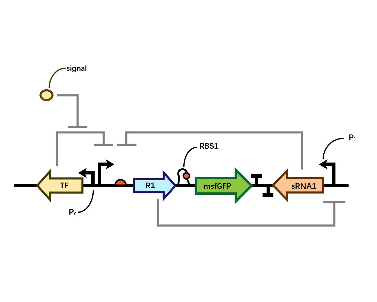
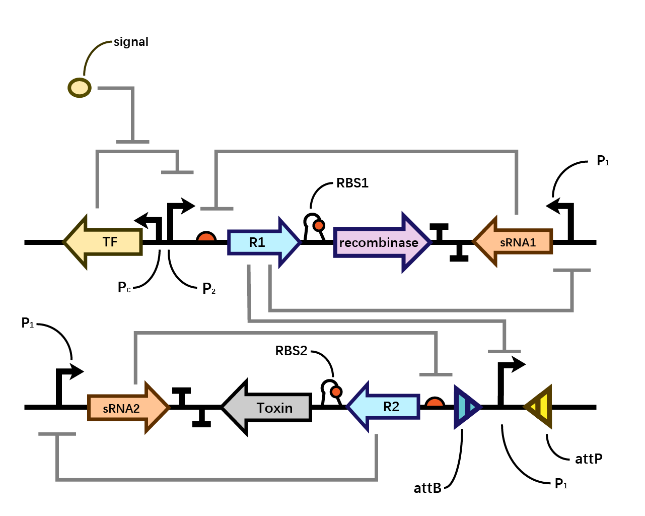
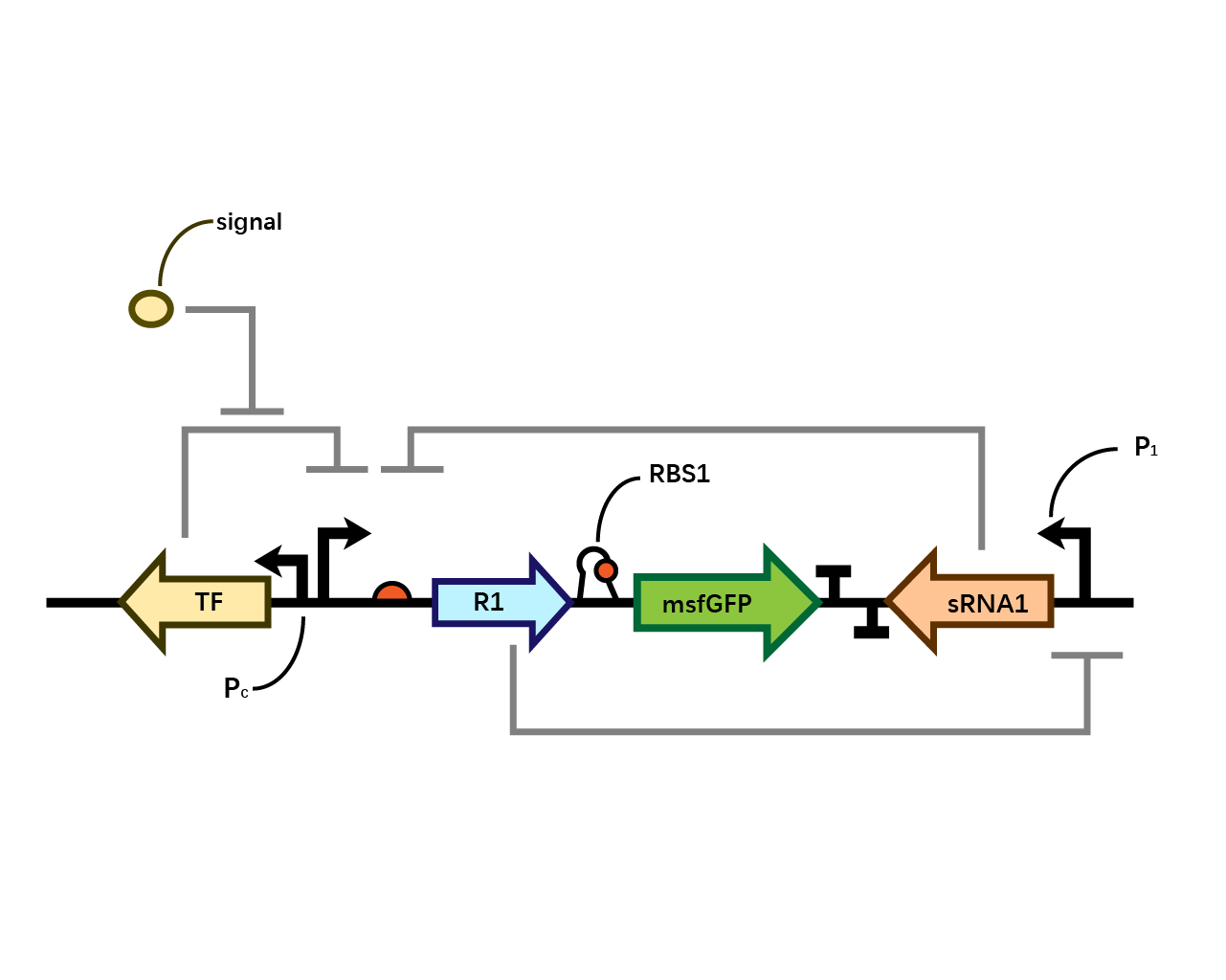
In our system(Fig. 1), we have transcriptional repressor R1 expressed through the inducible promoter but translationally inhibited by MicC sRNA1 since the RBS of R1 is directly inhibited by sRNA while they initiates the transcription of the two repressors; the gene of interest is translationally coupled to the repressor gene while three promoters which produces the inhibitory sRNA are targeted by their corresponding repressors. Therefore, repressors and sRNAs are mutually inhibitory.
RBS1
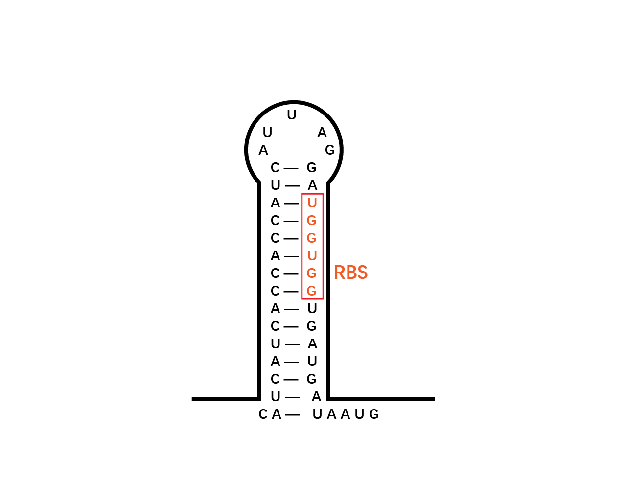
The control of the recombinase in coordination with the upstream repressor gene, which is the target of the sRNA, requires a translational coupler cassette. “An efficient mechanism to reach this goal is based on the ability of translating ribosomes to unfold mRNA secondary structures. In our design, translational coupling is achieved by occluding the RBS of gene of interest by formation of a secondary mRNA structure, containing a His-tag sequence added to the 3 ́end of the repressor gene. The hairpin structure prevents the ribosomal recruitment to the recombinase and therefore its translation. In contrast, when the upstream repressor mRNA is actively translated, the 70s ribosome disrupts inhibitory mRNA secondary structure in the downstream gene translation initiation region thus allowing its expression.”
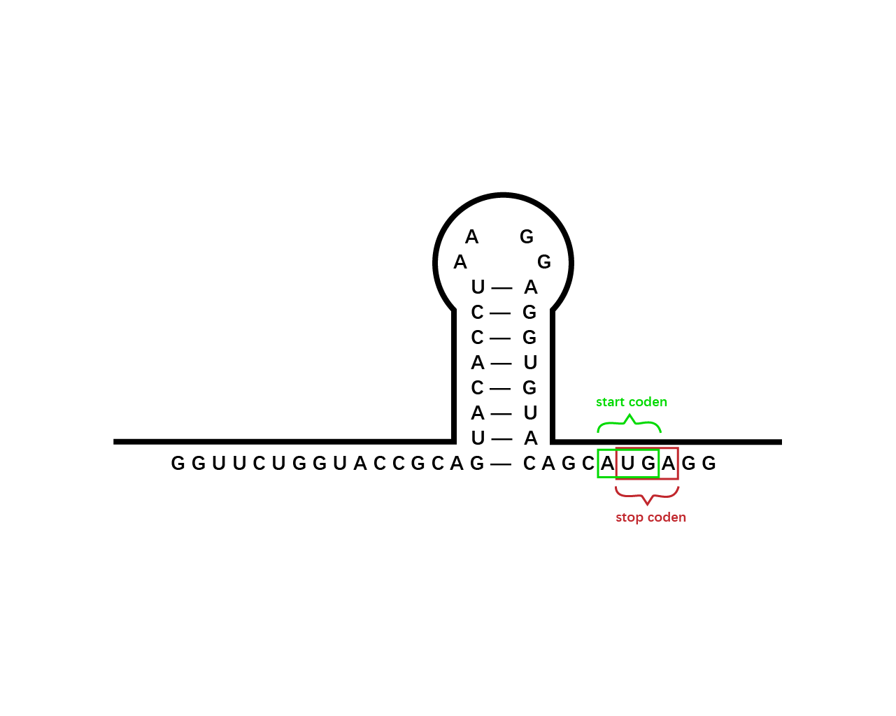
However, during the experiment we tested that the RBS1 (Fig. 2) sequence provided by the original article fails to function in our circuit, we found RBS2 (Fig. 3) with a different working mechanism. The structure of AUGA in RBS2 acts as both the stop codon (AUG) of the former gene sequence, releasing the former peptide chain; takes a step (gene code) backward, pinpointing a new ribosome binding site, and initiated the translation of next gene sequence with the start codon (UGA). However, finally we still used RBS1 since the crux actually lied in another place.
sRNA
Small non‐coding RNAs (sRNAs) have important functions as genetic regulators in prokaryotes. “sRNAs act post‐transcriptionally through complementary pairing with target mRNAs to regulate protein expression. Antisense sRNAs negatively regulates proteins by destabilizing the target protein's mRNA. Antisense sRNAs prevent translation by binding to the target mRNAs in a process mediated by the RNA chaperone Hfq.” On binding, both the mRNAs and sRNAs are degraded, suggesting that prokaryotic sRNAs—unlike their eukaryotic counterparts—act stoichiometrically on their targets.
Repressor
“A DNA-binding repressor blocks the attachment of RNA polymerase to the promoter, thus preventing transcription of the genes into messenger RNA.”
We assume that when the whole system is applied to a factory, the situation where inducer is present is in the working condition of the bacterium. Within one single layer of the bistable system, the transcriptional factor is turned on, Pm initiates the expression of R1, which raises the concentration of R1 and thereby exerts greater inhibition on PR1 and therefore decreases the concentration of sRNA1. As sRNA1 is inhibited the inhibitory effect it exerts on R1 accordingly decreases, therefore the recombinase is expressed through the first layer, and vice versa. Nevertheless, given that the expression of R1 inhibits PR1, even if the recombinase is expressed PR1 can be flipped over but cannot express the second layer. Since there is no further input signal to the second layer of the bistable system, the inhibitory effect of sRNA2 dominates over R2, therefore, both R2 and the toxin cannot be expressed. That is to say, the additional second layer ensures that there is no leakage of toxin when inducer is present.
However, when the bacterium is stolen and thereby inducer isn’t present, the transcriptional factor is turned off, promoter Pm doesn’t work. Therefore, sRNA1 dominates over R1 and then the recombinase is not expressed in the first layer. Since there is a decrease in the expression of R1, the inhibitory effect it exerts on PR1 decreases, therefore PR1 which has already been flipped over when inducer is present (working condition) initiates the expression of R2. Applying the same logic, finally R2 dominates over sRNA2 and expresses the toxin to kill the cell. (Fig. 4)
Why double layer?
The reason why we designed such double-bistable system can be attributed to the consideration that the double-decked bistable systems of both recombinase and toxin could further reinforce the insurance of zero expression of toxin.
When the second bistable system coupling the toxin with the first layer of recombinase, double insurance of zero expression of recombinase and toxin is achieved. However, as the diagram shown below, a single bistable system where toxin is coupled without the second layer of insurance could collapse if the mutual inhibitory effect of repressor and sRNA within the first layer malfunctions. Whereas such concern could be eliminated by the second layer of toxin with a bistable system around.
III. Experiment & Results
After the circuit (Fig. 5) including only one layer of the bistable system is constructed with recombinase being replaced by sfGFP, LacI & TetR serving as repressor, and used 3MBz & AraC as inducers, we qualitatively tested the fluorescence of the reporter protein under two situations when excited blue light. Theoretically, sfGFP should be expressed when inducer is present since LacI, which transcribes sfGFP, dominates over the inhibitory force of sRNA. However, in the experiments when inducers are present and absent, there is no fluorescence of sfGFP (BN027/Contains BBa_K3202074 & 28/Contains BBa_K3202075 & 29/Contains BBa_K3202076 & 30/Contains BBa_K3202077). We deduced that there must be defects lying in our circuit.
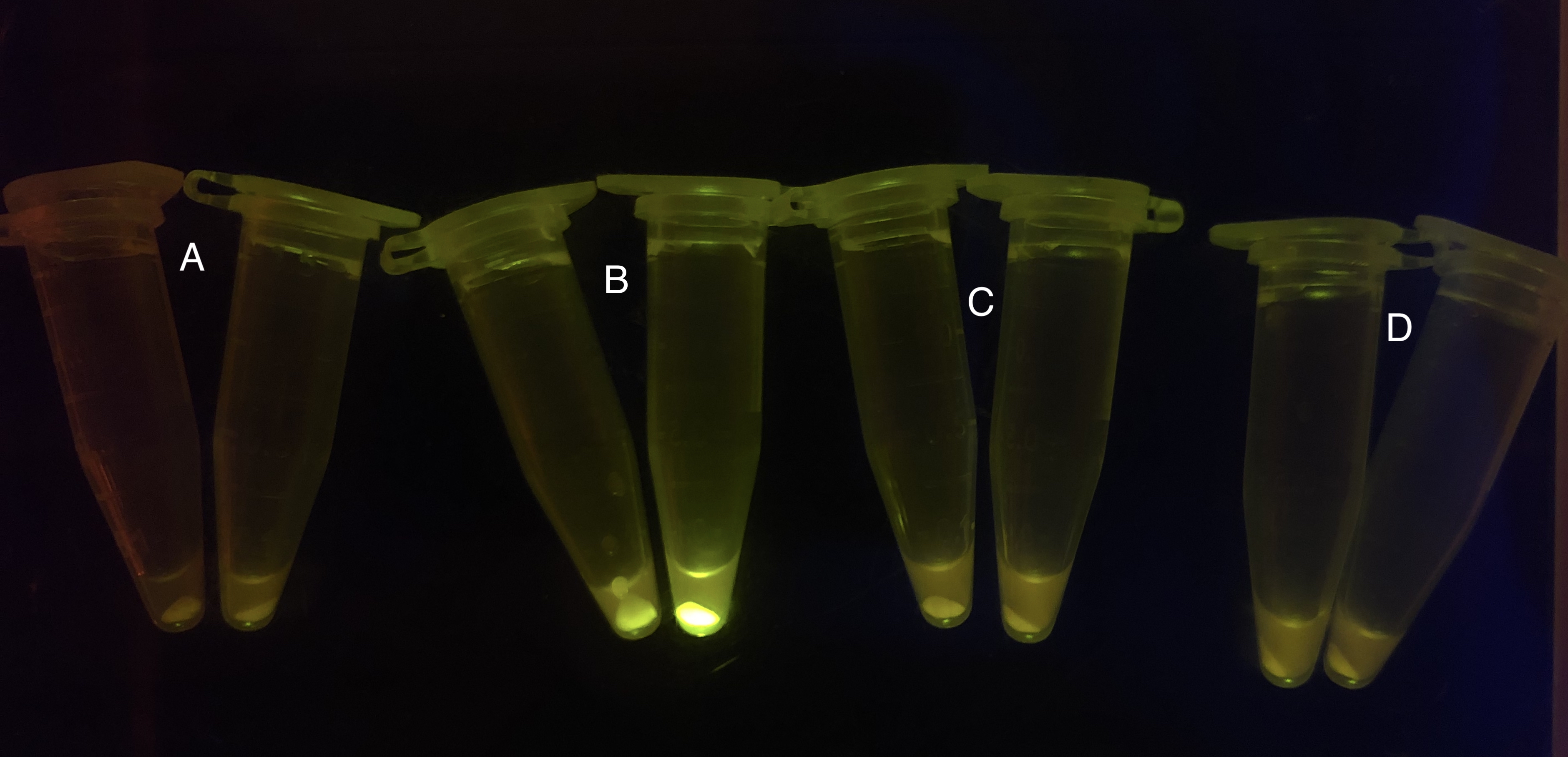
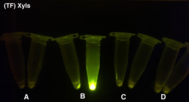
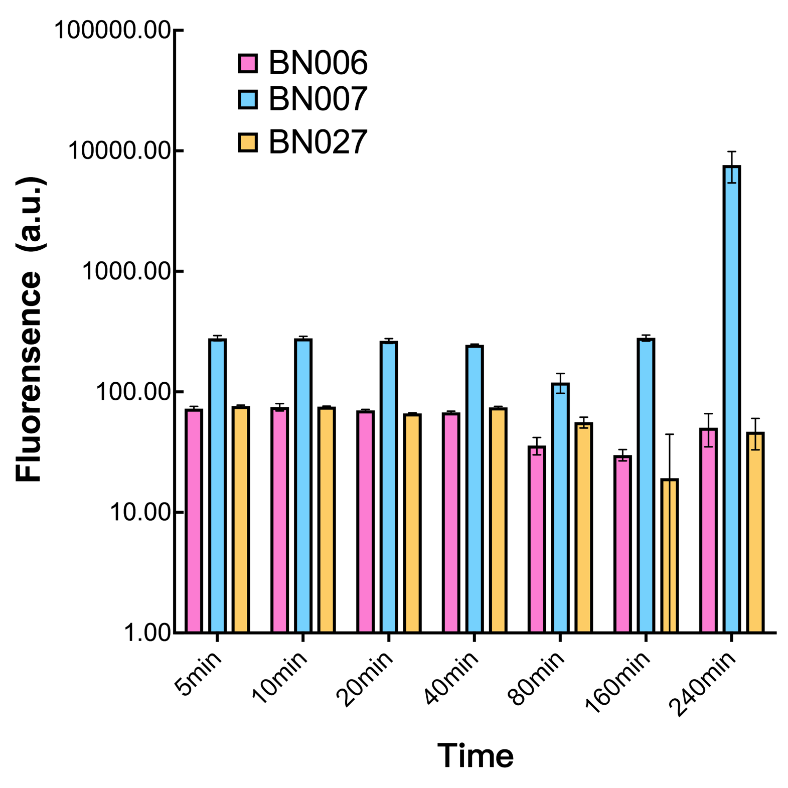
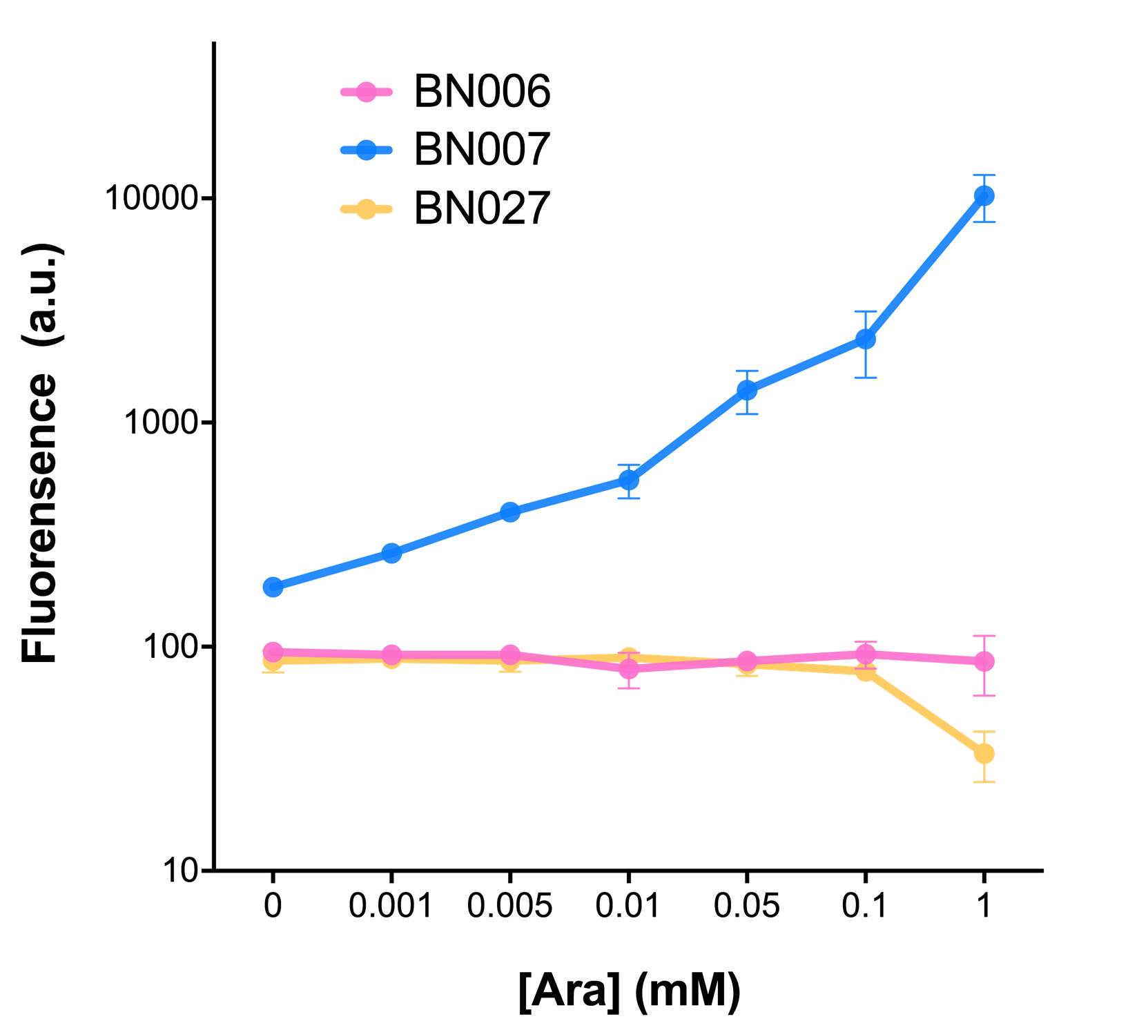
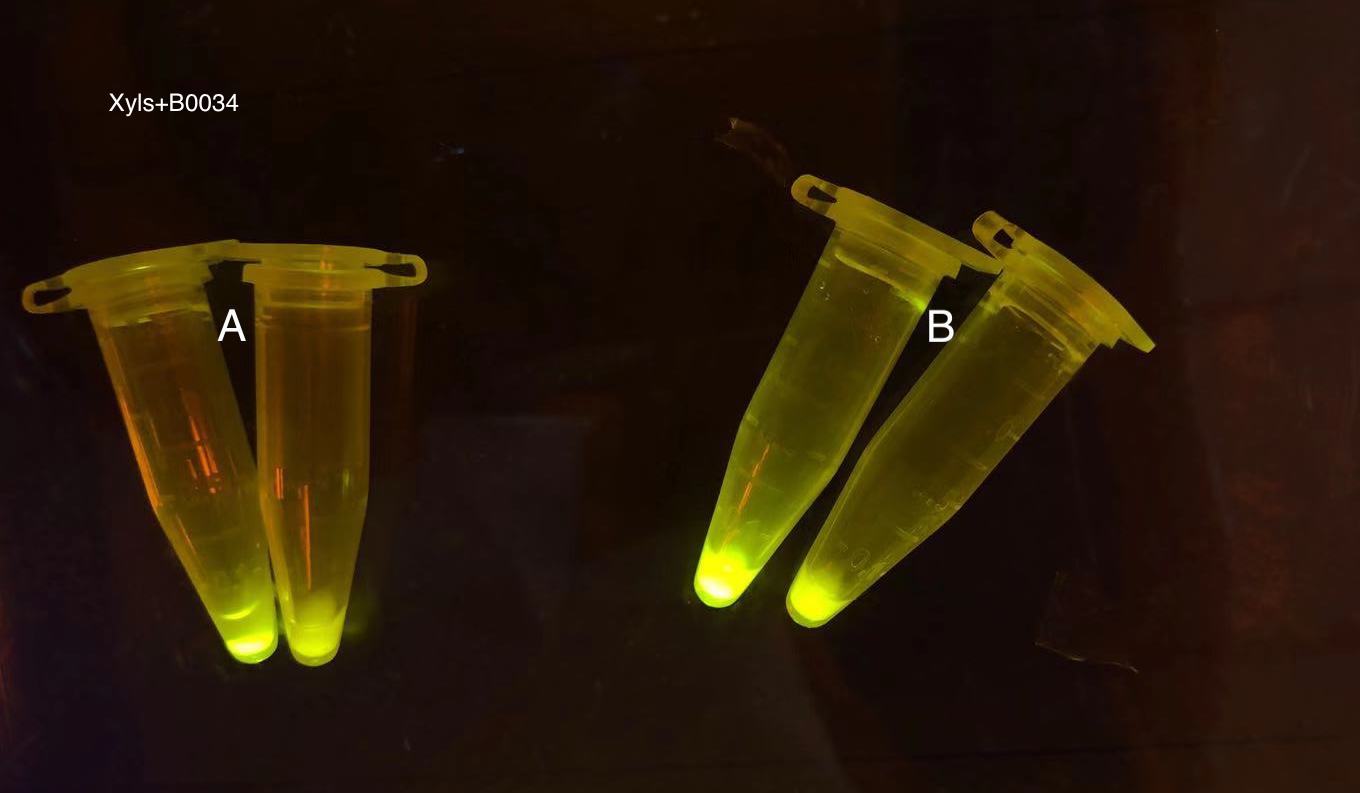
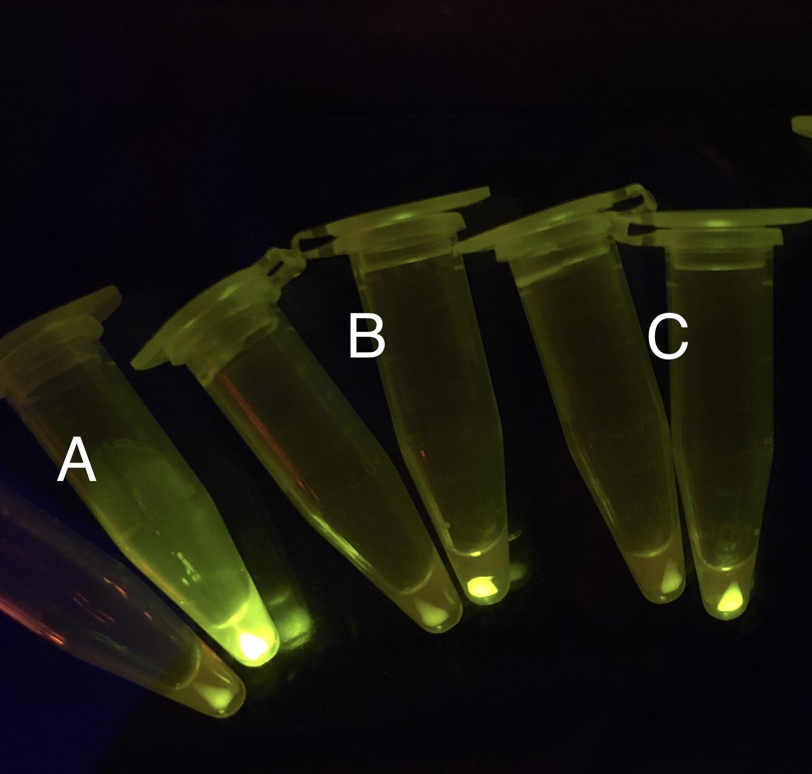
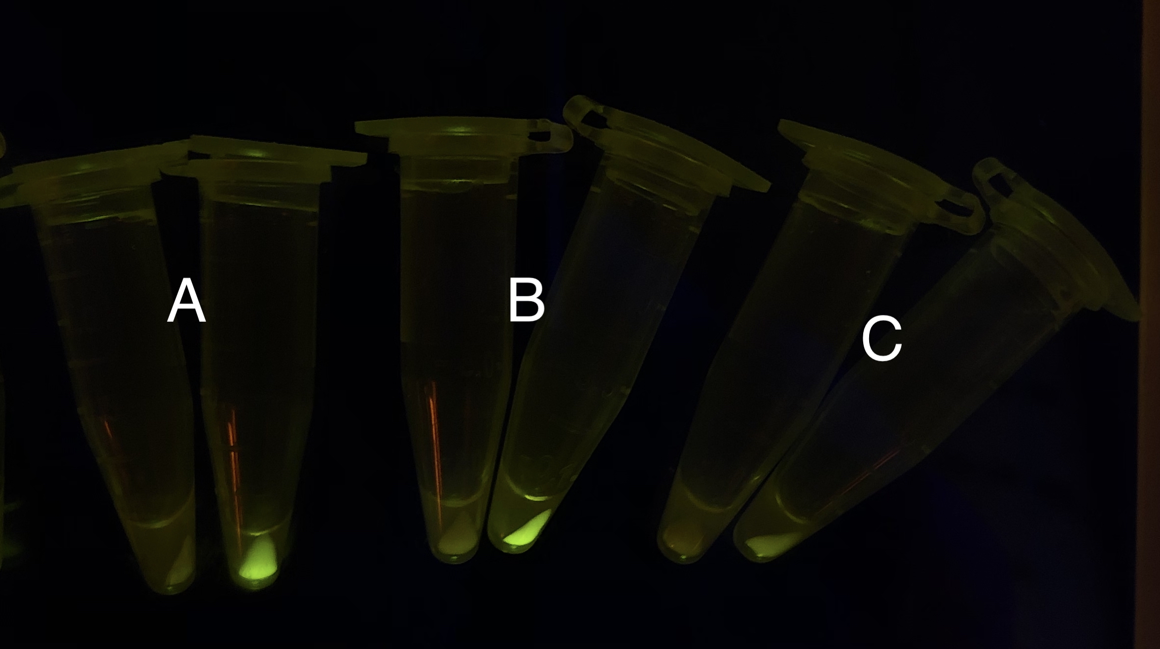
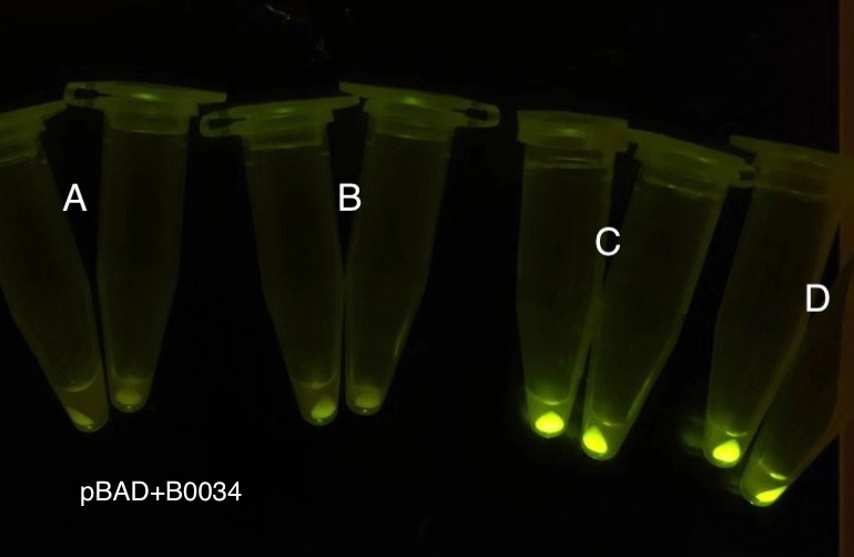
Analyzing through the whole circuit, we deduced that the crux might lie in RBS1 for the sake of its overwhelmingly strong hair-pin structure that even if the 3’ end of LacI is translated the ribosomes produced still couldn’t melt sRNA secondary structure, thereby sfGFP cannot be translated. Therefore, we replaced RBS1 with a commonly used RBS: B0034 with weaker strength in order to ensure that there is no problem lying in other sites in the circuit. We tested the sfGFP’s fluorescence in inducers’ presence under excitation of blue light. The expression of sfGFP in the second attempt (Fig. 10B, Fig. 11B & D) proved to us that there’s nothing wrong with the rest of the circuit except for RBS1.
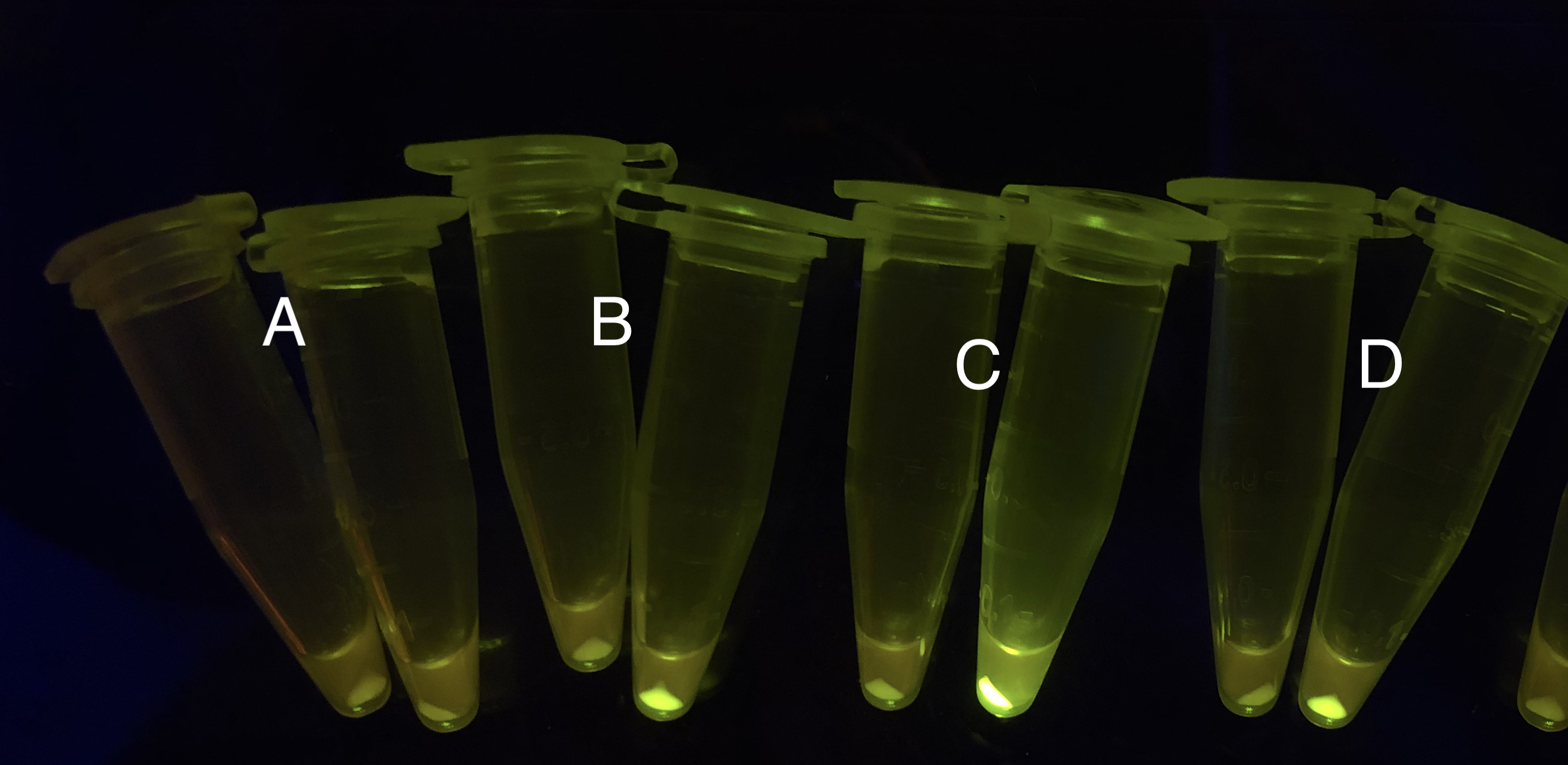
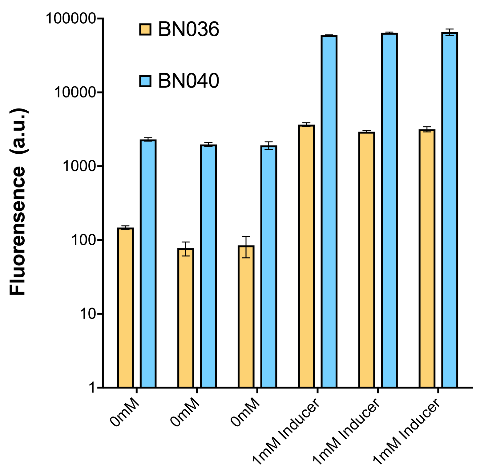
Through further searching we found that RBS2 has a weaker hair pin structure while it could support the translation of repressor. We replaced RBS B0034 with RBS2. Results are shown in the two graphs below. Plasmid with RBS2 expressed sfGFP with quite a high expression leakage when both inducers are absent. We thought that such high expression leakage might be the result of the weak hair-pin structure of RBS2, which means that we still need a strong RBS to reduce expression leakage. Hence, by we were inspired to realize that we might wrongly include the terminator of LacI before RBS. If we include the terminator, the transcription of LacI stops there and therefore the LacI protein produced by translation ends in front of RBS and leaves the mRNA secondary structure before melting it, sfGFP failed to be expressed.
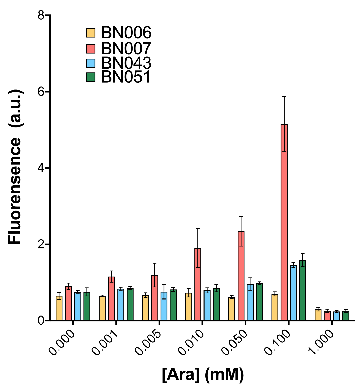
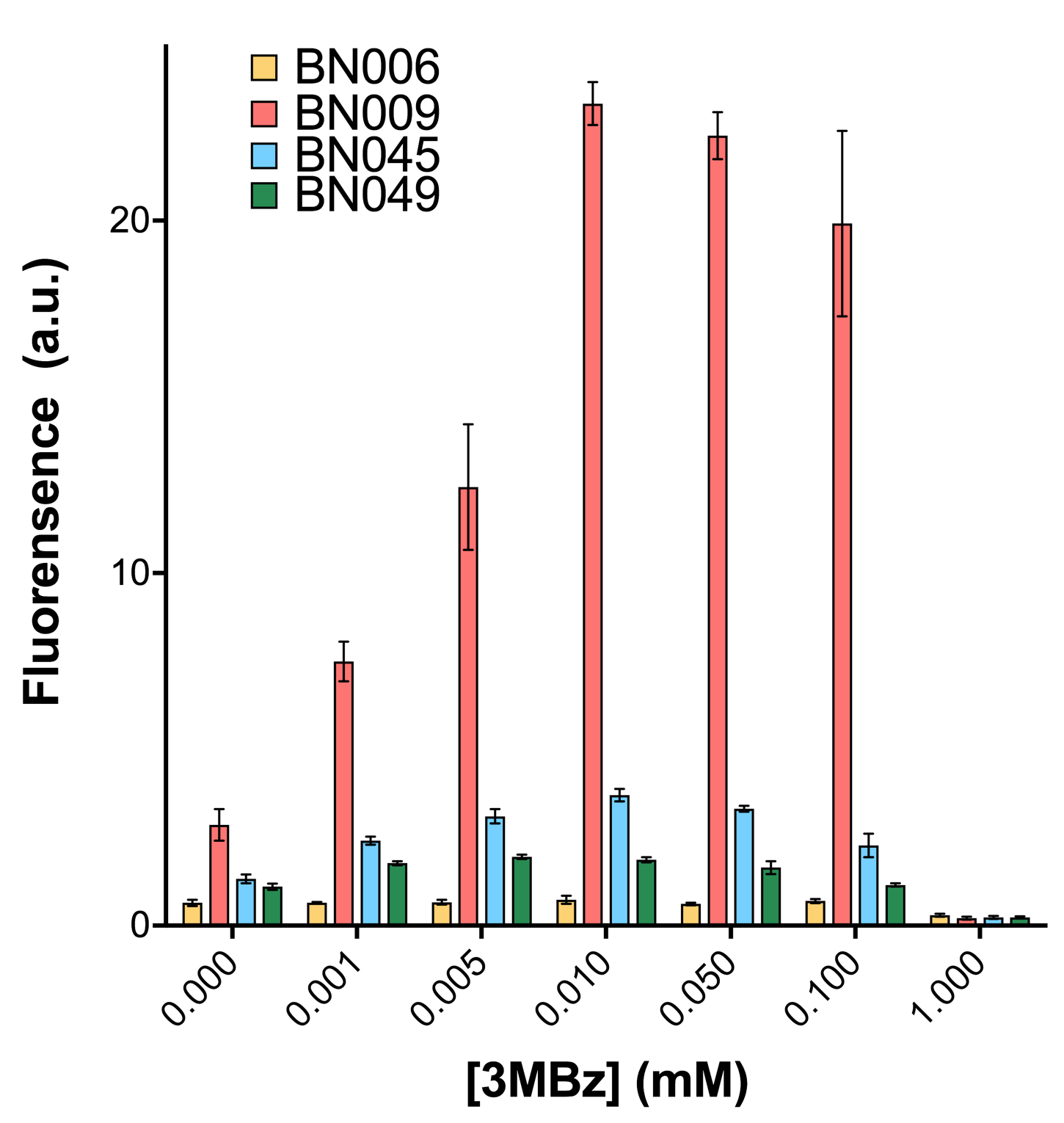
As shown in Fig. 15 & 16 from flow cytometry experiments: at the same time period, the conc. of inducer increases from 0.000 to 1.000 mMol, BN006/Contains BBa_K3202029, which carries no sfGFP, has a low fluorescence level around 0.60 a.u. in inducer’s absence. BN007/Contains BBa_K3202030 and BN009/Contains BBa_K3202031 without the control of bistable system had their fluorescence value at a relatively higher level in inducer’s absence and their fluorescence value increase as conc. of inducers increases. BN043/Contains BBa_K3202048 & 51/Contains BBa_K3202051 & 45/Contains BBa_K3202049 & 49/Contains BBa_K3202050 (under the control of bistable system) have their fluorescence value lower than that of BN007/Contains BBa_K3202030 and BN009/Contains BBa_K3202031 in inducer’s absence and have their fluorescence value as conc. of inducer increases.
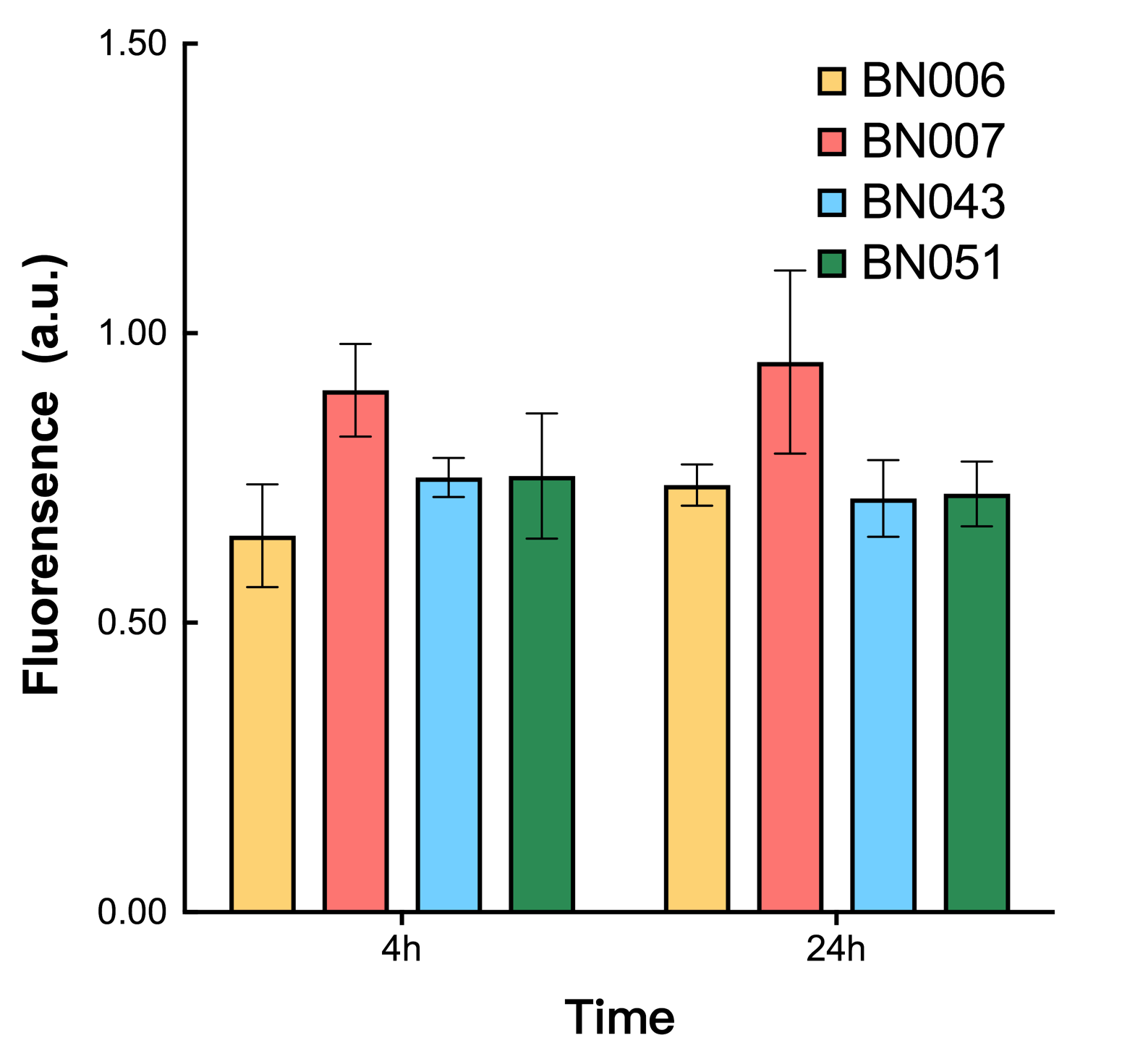
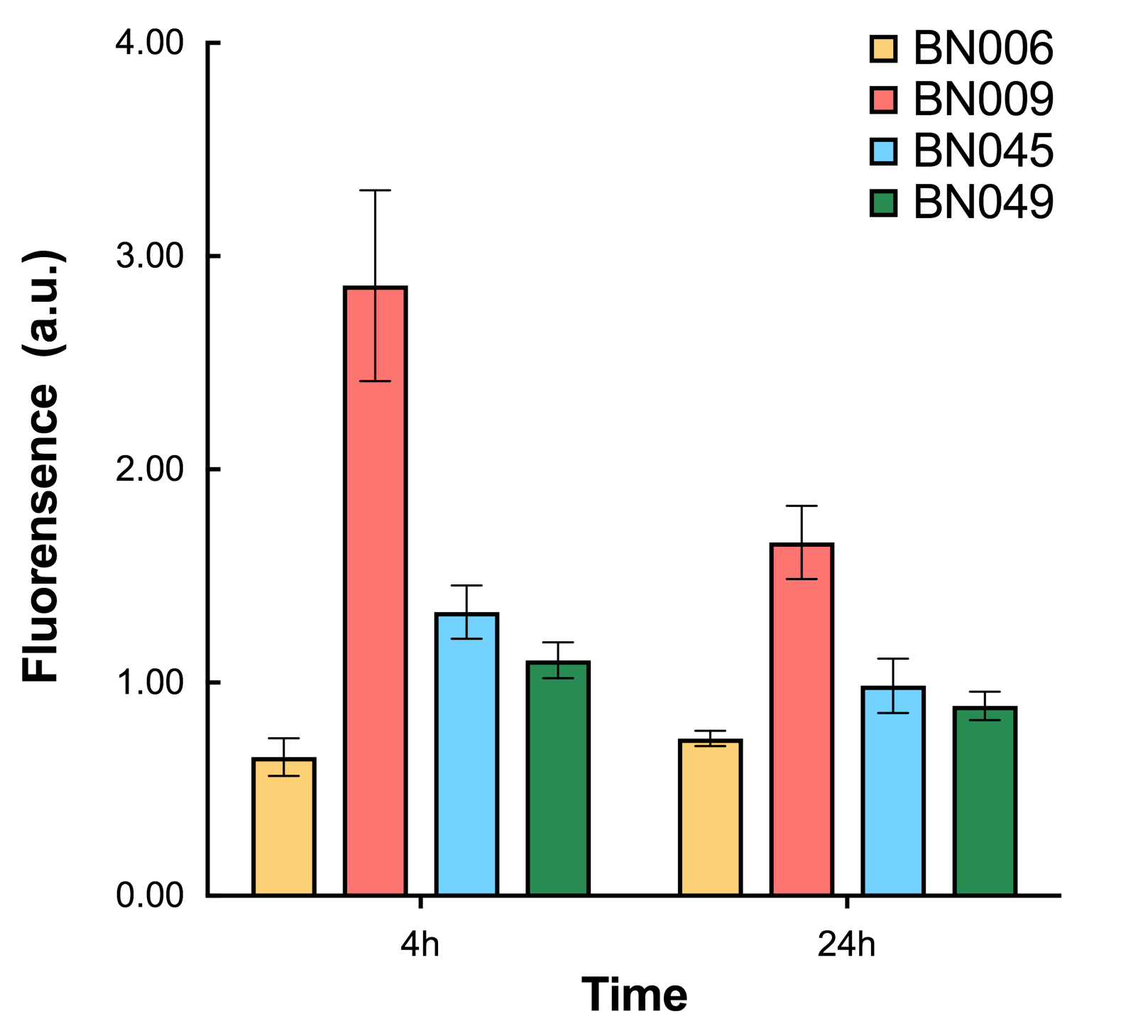
As shown in Fig. 17 & 18 from flow cytometry experiments: in the absence of inducer at the indicated time points (4h and 24h after induction), BN006/Contains BBa_K3202029, which carries no sfGFP, has a low fluorescence level around 0.60 a.u. in inducer’s absence. BN043/Contains BBa_K3202048 & 51/Contains BBa_K3202051 & 45/Contains BBa_K3202049 & 49/Contains BBa_K3202050 (under the control of bistable system) have their fluorescence value higher than that of BN006/Contains BBa_K3202029 while lower than that of BN007/Contains BBa_K3202030 &BN009/Contains BBa_K3202031 (without the control of bistable system) in inducer’s absence.
We improved our gene circuit upon that reflection, with exclusion of the terminator of repressors and replacement of BRS2 using RBS1, and made the third trial. The results are shown below.
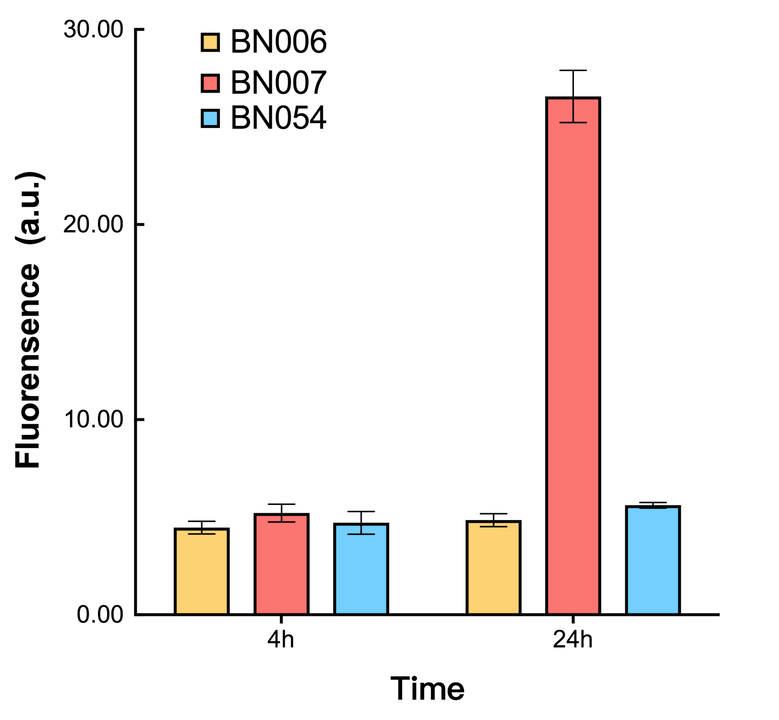
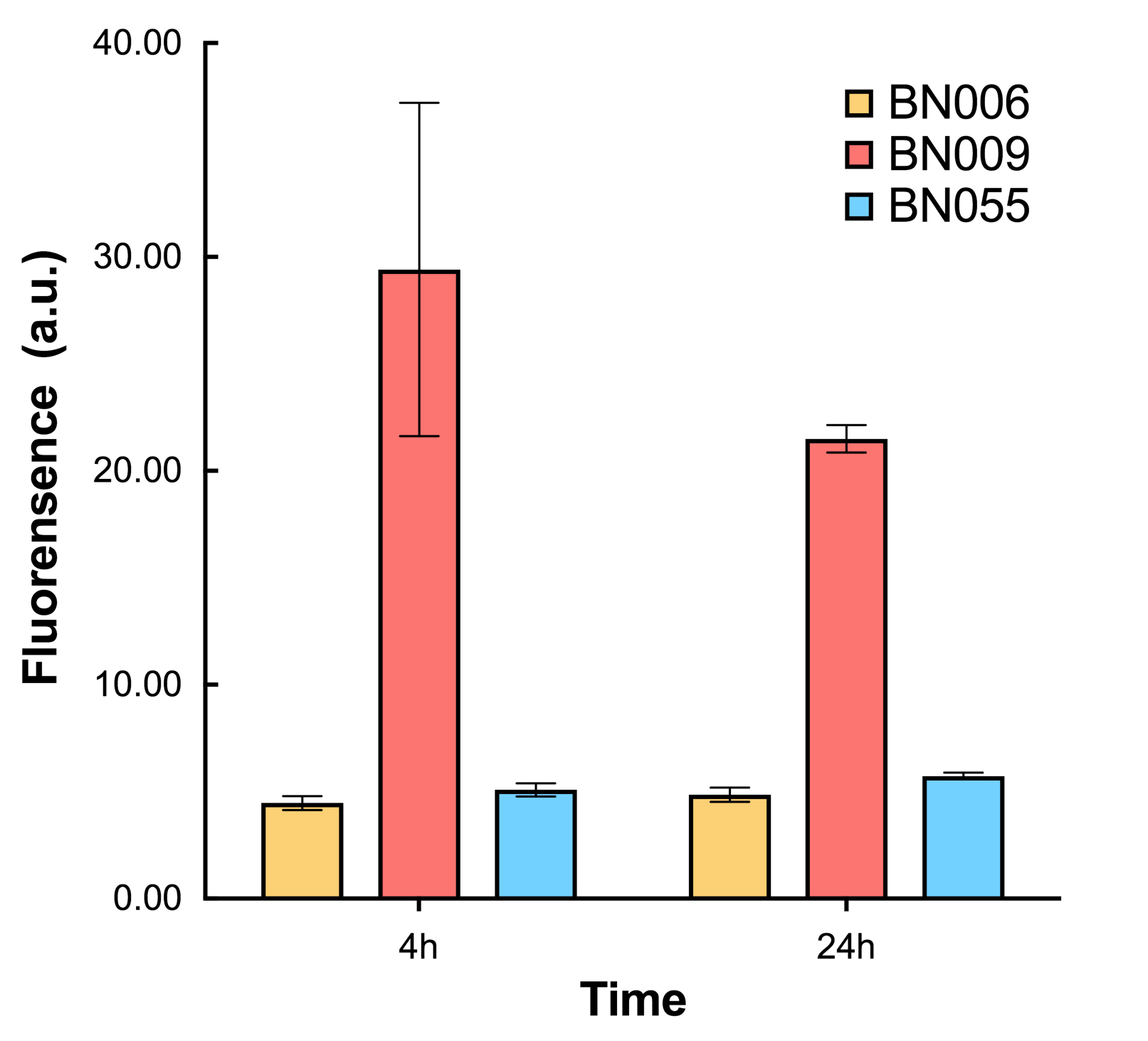
As shown in Fig. 20 & 21 from flow cytometry experiments: in the absence of inducer at the indicated time points (4h and 24h after induction), BN006/Contains BBa_K3202029, which carries no sfGFP, has a low fluorescence level around 0.60 a.u. in inducer’s absence. BN007/Contains BBa_K3202030 and BN009/Contains BBa_K3202031are two plasmids without the control of bistable system; they displayed high fluorescence level as time passed. BN054/Contains BBa_K3202044 and BN055/Contains BBa_K3202045 have similarly no fluorescence level as BN006/Contains BBa_K3202029.
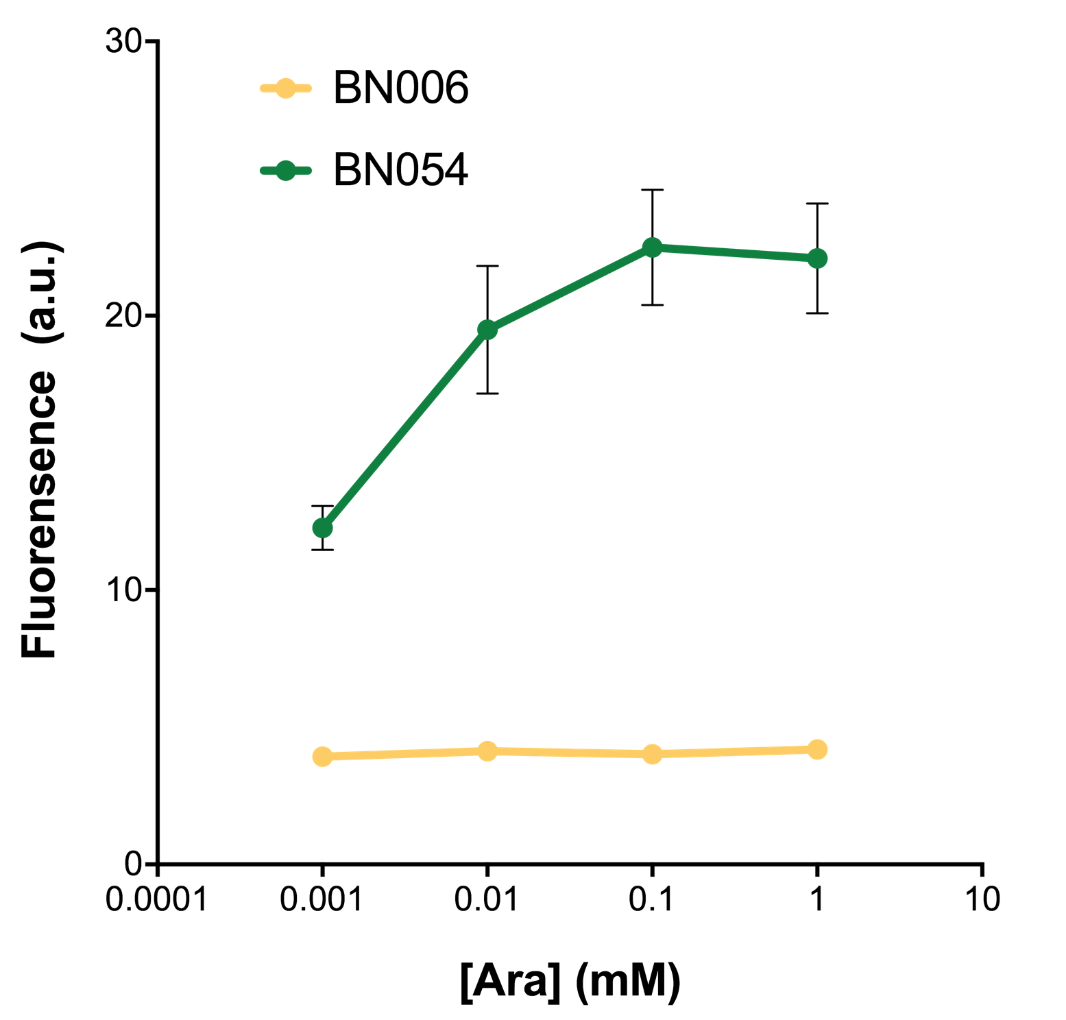
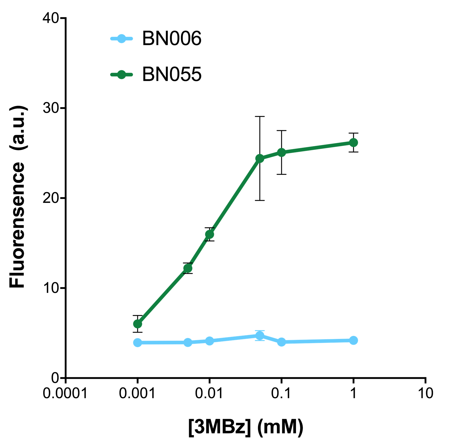
As shown in Fig. 22 & 23 from flow cytometry experiments: at same time period, as the conc. of inducers increases from 0.0001 (nearly no inducer) to 10 mMol, BN006/Contains BBa_K3202029, which carries no sfGFP, always has a low fluorescence level around 0.60 a.u. While both two plasmids (BN054/Contains BBa_K3202044, induced by Ara; BN055/Contains BBa_K3202045, induced by 3MBz) have their fluorescence level increase from around 10 a.u. (lack of expression of sfGFP) when inducer is absent to a higher value.
Recombinase Flipping Module
I.Background
We sought for a structure which could implement permanent memory on changes in our circuit while effectively connects our double bistable system and were inspired by the design of recombinase in Peking 2017. We tested three types of recombinase, Bxb1, TP901, PhiC31 they had in their project in our experiment.
Scientists discovered that phages phiC31 integrase make use of LSTP integrases in mediating phage integration and excision into the bacterial genome between their cognate recognition sites, attB (bacterium) and attP (phage). “By placing these sites in the opposite orientation, LSTP integrases cleave, rotate and rejoin the DNA to invert the region between sites. As shown in figure 1, LSTP integrases catalyze insertion of phage genome (yellow) into the bacterial genome (blue) between attB and attP sites, which form hybrid attL and attR sites. Multicolored arrowheads illustrate the sequence changes that occur during strand exchange, with the core sequence shown in yellow.”
We make use of the property of irreversible recombinase which can implement permanent memory so that before reverting the recombinase the second layer, the DNase, is inhibited in working condition, and after reverting the second layer can be eternally expressed, preventing the bacterium from reviving through other techniques.
II.Design
In our team, we include the recombinase in order to "implement the permanent memory of the circuit by irreversibly inverting the orientation of the intervening PR1 according to article Permanent genetic memory with >1-byte capacity." The recombinase is able to flip the DNA in only one direction and thus implement permanent memory.
When it is applied to our circuit, P1 is inverted in regular working condition where inducer is present, recombinase catalyzes the cleavage of each cognate recognition sites attB and attP, inverting the orientation of P1 and rejoining the circuit at attL and attR respectively. Due to the fact that irreversible recombinase can only flip the DNA in one direction, the inverted P1 which is inhibited in working condition where inducer is present remains inverted even when the recombinase is not expressed as inducer is absent. When the inducer is absent, R1 doesn’t inhibit the expression of the inverted P1 anymore, the toxin in the second layer can be then expressed and conduct suicide. The inversion is a permanent effect on the bistable system, that is to say even if we stimulate the whole system again by adding inducer, P1 will not switch its orientation back.
III.Experiment & Results
We used pBAD and PLtetO as promoters to regulate the expression of the three recombinases in order to test the effect flipping over the promoter J23119 (P1) by the three recombinases and to see if there is expression leakage.
Theoretically speaking, when inducer is present, recombinase should be expressed and successfully reverts the promoter P1 in-between, the bacterium will express mRFP, displaying red color; while if no inducer is present, the inhibitory effect the transcriptional factor exerts on P2 will stop the expression of recombinase, P1 fails to reverse, the bacterium will therefore express sfGFP, displaying green color.
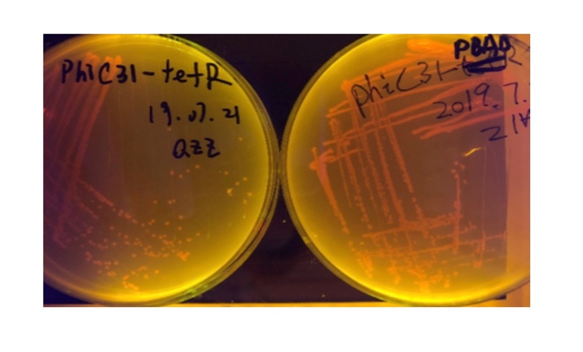
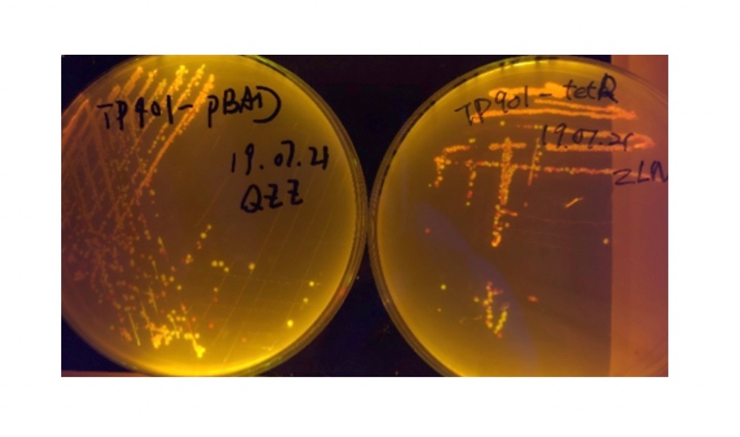
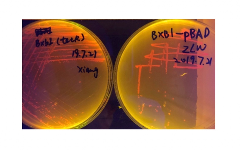
In the plating medium with no inducer, the leaked expression of recombinase reverted the promoter J23119, displaying red color. Comparing the three sets of recombinases (Fig. 3&4&5), we found that TP901 has the lowest expression leakage.
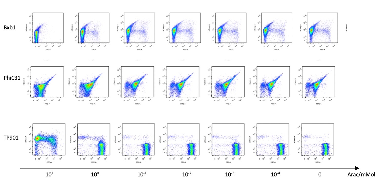
Then we used pBAD to test the recombinases’ working efficiency in inducer’s presence through flow cytometry. Results are quantitatively shown in the diagram below.
IV.Discussion
Our recombinases can effectively invert the in-between promoter under our design and experimental validation. This feature works well as a reactor for changes in the external environment. It permanently changes the sequence of genes and thus the direction of gene expression, which implements our goal of connecting two bistable system and exerting permanent effect on the circuit.
Sequence and Features
- 10COMPATIBLE WITH RFC[10]
- 12INCOMPATIBLE WITH RFC[12]Illegal NheI site found at 999
Illegal NheI site found at 1022
Illegal NheI site found at 3131 - 21INCOMPATIBLE WITH RFC[21]Illegal BglII site found at 930
Illegal BamHI site found at 2857
Illegal XhoI site found at 2770 - 23COMPATIBLE WITH RFC[23]
- 25INCOMPATIBLE WITH RFC[25]Illegal NgoMIV site found at 208
Illegal NgoMIV site found at 2131
Illegal NgoMIV site found at 2218
Illegal AgeI site found at 3081 - 1000INCOMPATIBLE WITH RFC[1000]Illegal BsaI site found at 1775
Illegal BsaI site found at 2023
| None |

