Difference between revisions of "Part:BBa K3168004"
EvaHanckmann (Talk | contribs) |
EvaHanckmann (Talk | contribs) |
||
| Line 47: | Line 47: | ||
<strong>Variable protein concentrations</strong> | <strong>Variable protein concentrations</strong> | ||
<br> | <br> | ||
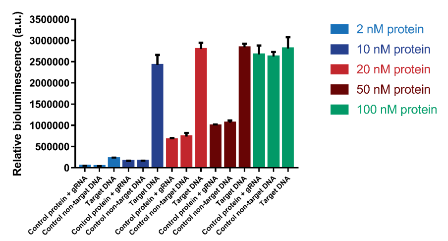
| − | It was tested which range of protein concentrations would be suitable for testing. | + | It was tested which range of protein concentrations would be suitable for testing. Concentrations of 2, 10, 20, 50 and 100 nM were tested with a DNA concentration of 1.2 nM. The results show that a protein concentration of 10 nM has the best signal-to-noise ratio (Figure 7). At higher protein concentrations, an increase in background signal can be observed without a significant increase in signal. For 100 nM, the background signal is as high as the actual signal, indicating that higher protein concentrations do not increase the sensitivity of the sensor. |
[[File:T--TU_Eindhoven--Variable protein concentrations.png|500px|]] | [[File:T--TU_Eindhoven--Variable protein concentrations.png|500px|]] | ||
Revision as of 15:11, 21 October 2019
dCas9-LargeBitNanoLuc
This composite part is made up of two basic parts (figure 1). The first basic part (BBa_K3168000) codes for a catalytically dead CRISPR associated protein 9 (dCas9). dCas9 binds to a specific double-stranded DNA sequence which is determined by the guide RNA. The second basic part (BBa_K3168002), which is fused to dCas9, consists of a (GGS)5 linker and the large bit of NanoLuc. When the large bit of Split-NanoLuc forms a complex with the small bit and the substrate Furimazine is present, blue light is emitted. dCas9-LargeBit itself is slightly bioluminescent when the substrate is added. However, the intensity is more bright when a complex is formed with the small bit. Thus this composite part is part of a Split-NanoLuc detection system, which targets a specific sequence on dsDNA and sends out a bioluminescent signal upon binding of this specific sequence (figure 2).
Figure 1. Schematic representation of dCas9-LargeBitNanoLuc.
Usage and Biology
dCas9 in combination with guide RNA forms a dsDNA recognition complex. A stronger bioluminescent signal is created when dCas9-LargBitNanoLuc and dCas9-SmallBitNanoLuc bind in close proximity.
Figure 2. Schematic representation of dCas9-Split-NanoLuc system.
Characterization
Expression
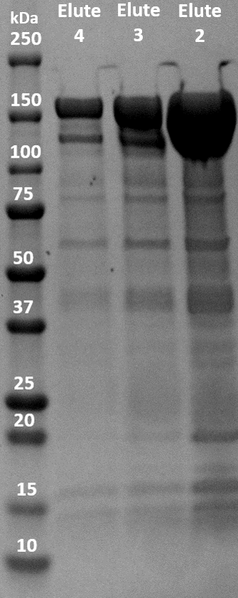
The fusion protein was successfully expressed in BL21(DE3) and purified with immobilized metal affinity chromatography (IMAC). The elution was collected in 5 fractions of 1.5 mL. The three elution samples with the highest concentrations were put on an SDS-PAGE gel to evaluate the purity and molecular weight of the samples. dCas9-LargeBitNanoLuc has a molecular weight of 178 kDa. As shown in figure 3, there are very obvious blobs of dCas9-LargeBitNanoLuc above 150 kDa. There are other bands visible so the purity is not optimal. However, the contrast between the huge blobs and the other bands is very big.
Figure 3. SDS-PAGE gel of IMAC elution samples of dCas9-LargeBitNanoLuc (Elute 2: 17.90 μM, Elute 3: 6.37 μM, Elute 4: 2.88 μM).
Testing the paired dCas9-Split-NanoLuc system
To test the paired dCas9-Split-NanoLuc system, test DNA in the form of gBlocks were designed (Figure 4). The sequence of this test DNA was based on the T7 phage genome since the T7 phage is used for the proof-of-concept of dCastect. By using the T7 sequence, the same gRNA pairs can be used for all experiments. Using the gBlocks, the sensor was first optimized by varying the protein concentrations and interspace distance. Subsequently, the limit of detection could be determined, followed by tests where the sensor proteins bind to multiple recognition sites on the same target to see if an even smaller limit of detection could be reached.
Figure 4. Schematic representation of the design of the test DNA gBlocks.
Variable interspace distance
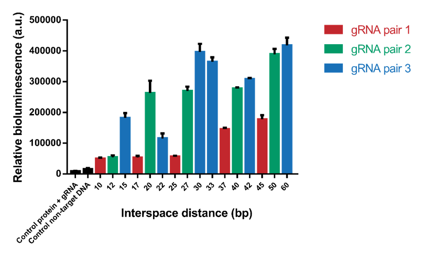
The interspace distance was varied between the two dCas9 domains to find the optimal distance for association of SmallBit and LargeBit. Because of the helical shape of DNA, a pattern with higher signals when the two proteins bind on the same side of the helix and lower signals when the two proteins bind on the opposite side of the helix was expected. Eventually for high interspace distances a lack of signal was expected, because the distance would be too big for association of SmallBit and LargeBit. In the first test interspace distances from 10 bp to 60 bp were tested (Figure 5). The tests were performed using a 1.2 nM DNA concentration, 2 nM protein concentration and 6x molar excess of gRNA. The results show that the systems containing an interspace distance lower than 20 bp give a low signal. From 20-60 bp the signal is high, which means that interspace distance is not a limitation for choosing desired gRNA sequences. Interspace distances 30, 50 and 60 give the highest signals.
Figure 5. Bioluminescence intensity measured with variable interspace distances. The interspace distance is the number of base pairs between the two gRNA pairs.
However, it can be observed that the different gRNA pairs cause a difference in signal (Figure 5). gRNA pairs 1 gives a significantly lower signal for all measurements. To test whether this lower signal is caused by the gRNA and not difference in interspace distance, the system containing interspace distance 30 was tested using all three different gRNA pairs (Figure 6). As can be seen, gRNA pair 1 gives a significantly lower signal than the other two gRNA pairs. gRNA pair 3 gives the highest signal, so it was decided to use this gRNA pair in future measurements.
Figure 6. The difference in bioluminescent signal for the three different gRNA pairs.
Variable protein concentrations
It was tested which range of protein concentrations would be suitable for testing. Concentrations of 2, 10, 20, 50 and 100 nM were tested with a DNA concentration of 1.2 nM. The results show that a protein concentration of 10 nM has the best signal-to-noise ratio (Figure 7). At higher protein concentrations, an increase in background signal can be observed without a significant increase in signal. For 100 nM, the background signal is as high as the actual signal, indicating that higher protein concentrations do not increase the sensitivity of the sensor.
Figure 7. The protein concentration was varied from 2 nM to 100 nM. Background signal containing only protein and gRNA and a control using non-target DNA were also tested.
Variable DNA concentrations
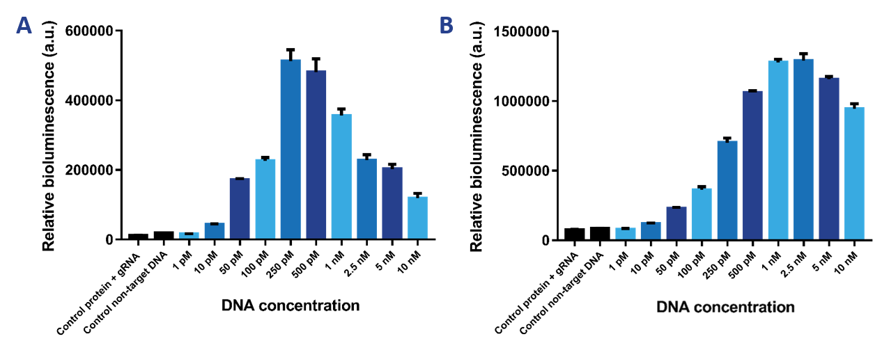
The limit of detection of our sensor was tested, which is the most important property of the sensor. Therefore, we tested a range of DNA concentrations from 1 pM to 10 nM using a protein concentration of 2 nM (Figure 8a) and 10 nM (Figure 8b). It was expected that the 2 nM sensor would be more sensitive than the 10 nM sensor and would therefore be able to detect lower DNA concentrations. The 10 nM sensor is better at detecting higher DNA concentrations. The limit of detection then is 50 pM. The 2 nM sensor can detect DNA concentrations as low as 10 pM. The Hook effect can be observed for both sensors, which is the decrease in signal at greater concentrations of the target compound. Due to the high availability of binding sites, the likelihood of either dCas9-SmallBit or dCas9-LargeBit binding at a binding site is higher. Therefore, SmallBit and LargeBit do not associate and a decrease in bioluminescent signal can be observed.
Figure 8. a) Bioluminescence intensity when the target DNA concentration is varied at a 2 nM protein concentration. b) Bioluminescence intensity when the target DNA concentration is varied at a 10 nM protein concentration.
Multiple sensor proteins
In previous experiments, the limit of detection was determined using one dCas9-SmallBit and one dCas9-LargeBit binding to the recognition sites on a target sequence. To determine if the limit of detection could be lowered when multiple sensor proteins would bind to multiple recognition sites on one target DNA strand, the limit of detection was tested using three pairs of sensor proteins binding to one target (Figure 9). The results show that the limit of detection is slightly lowered to 5 pM when three pairs of sensor proteins bind to multiple recognition sites on one target.
Figure 9. Bioluminescent intensity when three sensor protein pairs bind to three paired recognition sites.
References
Dixon, A. S., Schwinn, M. K., Hall, M. P., Zimmerman, K., Otto, P., Lubben, T. H., ... & Wood, M. G. (2015). NanoLuc complementation reporter optimized for accurate measurement of protein interactions in cells. ACS chemical biology, 11(2), 400-408.
Zhang, Y., Qian, L., Wei, W., Wang, Y., Wang, B., Lin, P., ... & Cheng, S. (2016). Paired design of dCas9 as a systematic platform for the detection of featured nucleic acid sequences in pathogenic strains. ACS synthetic biology, 6(2), 211-216.
Sequence and Features
- 10COMPATIBLE WITH RFC[10]
- 12INCOMPATIBLE WITH RFC[12]Illegal NheI site found at 1099
- 21INCOMPATIBLE WITH RFC[21]Illegal BamHI site found at 3378
Illegal BamHI site found at 4630 - 23COMPATIBLE WITH RFC[23]
- 25COMPATIBLE WITH RFC[25]
- 1000COMPATIBLE WITH RFC[1000]


