Difference between revisions of "Part:BBa K3304105"
Sophie2298 (Talk | contribs) |
PlatonMega (Talk | contribs) |
||
| (4 intermediate revisions by 2 users not shown) | |||
| Line 3: | Line 3: | ||
<partinfo>BBa_K3304105 short</partinfo> | <partinfo>BBa_K3304105 short</partinfo> | ||
| − | This is the Input Gate for our Chemical Reaction Network. The oligo input is DTG (part: ) | + | This is the Input Gate for our Chemical Reaction Network. The oligo input is DTG (part: BBa_K3304118 ) wich initiates the strand displacement cascades. Other auxiliary strands for this gate are BTD (part: BBa_K3304108 ) and NTB (part: BBa_K3304109 ) who conclude the reactions and facilitate their trajectory to the desired direction. The output of this gate is TBB (part: BBa_K3304110 ) which constitutes the input for the downstream Join Gate (part: BBa_K3304106 ). The part comes with two PvuII cut sites and three Nt.BstNBI nicking sites that facilitate the extraction of the gate from plasmid DNA and prepare the double-stranded block for strand displacement reactions. The ELK-1s binding site is incorporated at the TDD domain allowing for the ELK-1 TF to bind to the sequence, thus inhibiting the initiation of strand displacement reactions, reducing the concentration of available Input Gates and subsequently the amount input TBB, resulting in proportional circuit behavior. |
https://2019.igem.org/wiki/images/c/ca/T--Thessaloniki--animation-step1.gif | https://2019.igem.org/wiki/images/c/ca/T--Thessaloniki--animation-step1.gif | ||
https://2019.igem.org/wiki/images/0/02/T--Thessaloniki--animation-step2.gif | https://2019.igem.org/wiki/images/0/02/T--Thessaloniki--animation-step2.gif | ||
| − | https://2019.igem.org/wiki/images/3/38/T--Thessaloniki--animation-step3. | + | https://2019.igem.org/wiki/images/3/38/T--Thessaloniki--animation-step3.gif |
| + | https://2019.igem.org/wiki/images/6/60/T--Thessaloniki--results-f3.png | ||
| + | Performance of the ELK1-designated circuit with varying concentrations of the Input Gate. Circuit leaks were observed to be similar while the circuit’s performance was observed to be better for similar time scales. | ||
https://2019.igem.org/wiki/images/7/70/T--Thessaloniki--results-f5.png | https://2019.igem.org/wiki/images/7/70/T--Thessaloniki--results-f5.png | ||
| − | + | Comparison of the ELK1 designated circuit when the TF is used as the rate-limiting factor. Once again, one can observe the change in kinetic behavior after the TF insertion, proof that the designed circuit can be assessed through our model’s Genetic Algorithm in order to receive various TFs as input. Input Gate was set at 20nM concentration. The behavior of our system is observed close to the behavior of the system with 10nM input present. | |
<!-- Add more about the biology of this part here | <!-- Add more about the biology of this part here | ||
===Usage and Biology=== | ===Usage and Biology=== | ||
Latest revision as of 03:23, 22 October 2019
Input Gate with ELK1 sequence
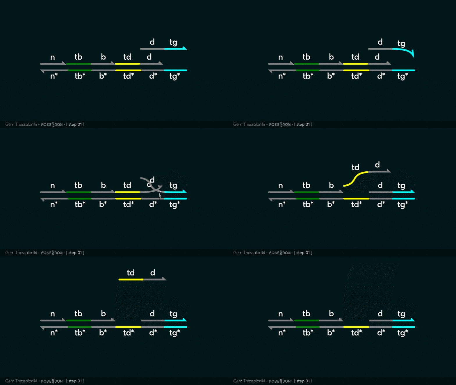
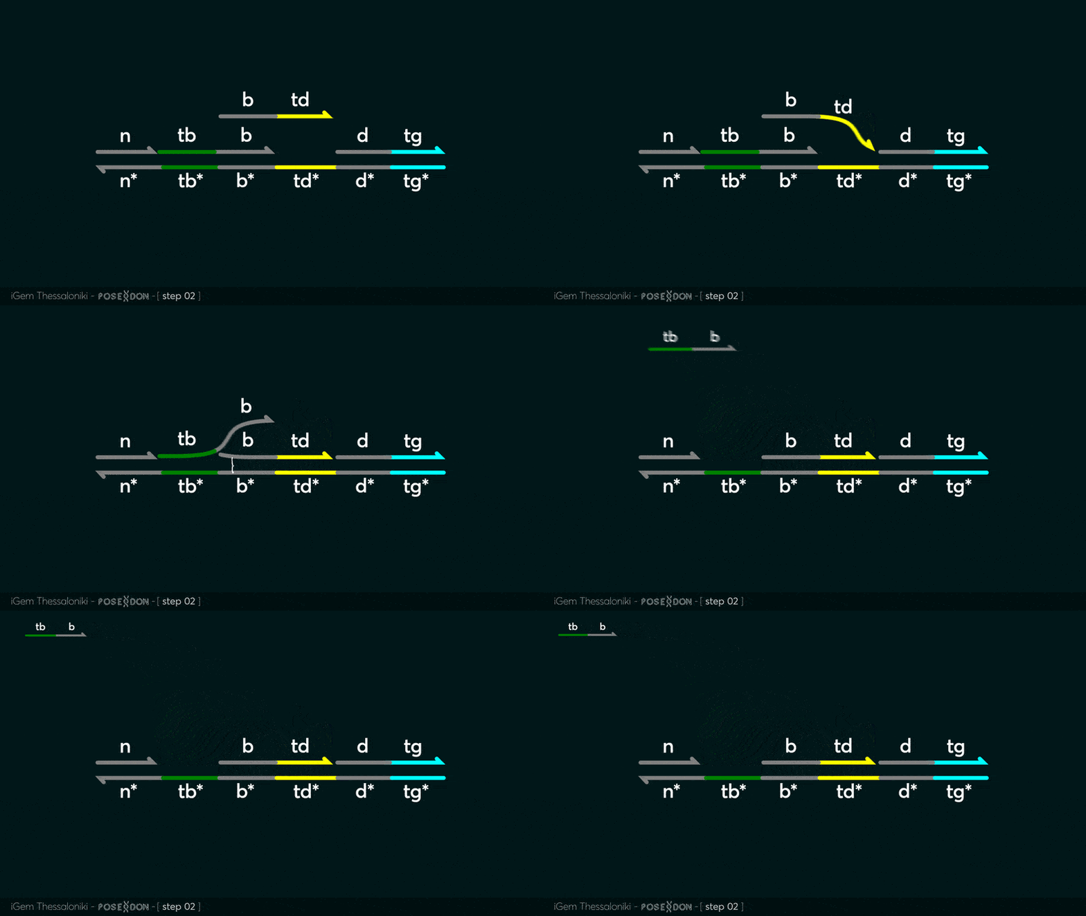
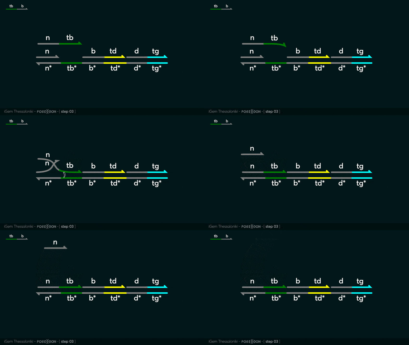
This is the Input Gate for our Chemical Reaction Network. The oligo input is DTG (part: BBa_K3304118 ) wich initiates the strand displacement cascades. Other auxiliary strands for this gate are BTD (part: BBa_K3304108 ) and NTB (part: BBa_K3304109 ) who conclude the reactions and facilitate their trajectory to the desired direction. The output of this gate is TBB (part: BBa_K3304110 ) which constitutes the input for the downstream Join Gate (part: BBa_K3304106 ). The part comes with two PvuII cut sites and three Nt.BstNBI nicking sites that facilitate the extraction of the gate from plasmid DNA and prepare the double-stranded block for strand displacement reactions. The ELK-1s binding site is incorporated at the TDD domain allowing for the ELK-1 TF to bind to the sequence, thus inhibiting the initiation of strand displacement reactions, reducing the concentration of available Input Gates and subsequently the amount input TBB, resulting in proportional circuit behavior.


 Performance of the ELK1-designated circuit with varying concentrations of the Input Gate. Circuit leaks were observed to be similar while the circuit’s performance was observed to be better for similar time scales.
 Comparison of the ELK1 designated circuit when the TF is used as the rate-limiting factor. Once again, one can observe the change in kinetic behavior after the TF insertion, proof that the designed circuit can be assessed through our model’s Genetic Algorithm in order to receive various TFs as input. Input Gate was set at 20nM concentration. The behavior of our system is observed close to the behavior of the system with 10nM input present.
Sequence and Features
- 10COMPATIBLE WITH RFC[10]
- 12COMPATIBLE WITH RFC[12]
- 21COMPATIBLE WITH RFC[21]
- 23COMPATIBLE WITH RFC[23]
- 25COMPATIBLE WITH RFC[25]
- 1000COMPATIBLE WITH RFC[1000]
