Difference between revisions of "Part:BBa K1886016"
| (2 intermediate revisions by one other user not shown) | |||
| Line 18: | Line 18: | ||
<partinfo>BBa_K1886016 parameters</partinfo> | <partinfo>BBa_K1886016 parameters</partinfo> | ||
<!-- --> | <!-- --> | ||
| + | <h2>'''Characterization'''</h2> | ||
| + | <h3> BACKGROUND </h3> | ||
| + | <h4>Overview</h4> | ||
| + | We simplified the three-plasmid system based on our reference by constructing all the segments in one plasmid. And we tested in E.coli MG1655. We used arabinose promoter (PBAD) and lactose promoter (Plac) as inducers and we have verified the corresponding concentration and time. | ||
| + | <br> | ||
| + | <h4>Principle</h4> | ||
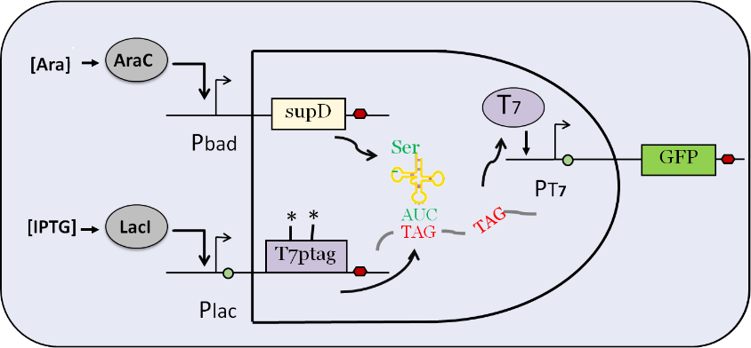
| + | This is the input part of AND GATE. After being induced by IPTG, plac promoter activates the expression of T7 RNA polymerase which contains two amber mutations (T7 ptag) . After being induced by L-arabinose, pbad promoter activates the expression of a special tRNA (supD), which is used to identify amber mutation. In the wild-type E.coli, amber mutation will inhibit the translation of T7 RNA polymerase. Therefore, only when the two inputs exist together, T7 RNA polymerase can be expressed, and then T7 promoter can be activated to express the downstream gene. | ||
| + | <br> | ||
| + | [[File:logic gate principle.png|800px|thumb|center|Fig.1 Fig.1 logic gate principle ]] | ||
| + | <h3>RESULTS</h3> | ||
| + | <h4>Gel electrophoretic analysis</h4> | ||
| + | <br> | ||
| + | [[File:K1886016.2.jpg|800px|thumb|center|Fig.2 Fig.2 Gel electrophoretic analyses of PCR products ]] | ||
| + | <br> | ||
| + | <h3> Precision of the Logic Gate </h3> | ||
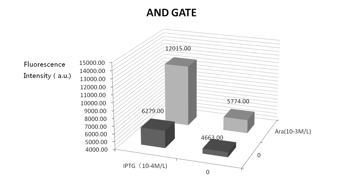
| + | We did four parallel experiments: the bacteria solutions were added by IPTG of 10^-3mol/L, arabinose of 10^-4mol/L, both of them, and neither of them. Following is the result. | ||
| + | <br> | ||
| + | [[File:logical gate new.png|800px|thumb|center|Fig.3 Fig.3 logical gate]] | ||
| + | <br> | ||
| + | Seeing from the figure, solutions with no inducers or only one inducer can produce little GFP fluorescence which verify the precision and feasibility of the AND gate. But, GFP fluorescence is high when only adding arabinose. This may because the leak of Plac. We will optimize our experiment by adding a weaker RBS between Plac and T7ptag. | ||
| + | <br> | ||
| + | <h3>Response Concentration</h3> | ||
| + | Next, we designed experiments to verify the response concentration. Through these experiments, we can also conclude under which concentration can the AND gate have the best effect. We designed a series of gradient about how many inducers should be added. The concentration of IPTG and arabinose varied from 10^-3, 10^-4, 10^-5, 10^-6, to 0. Following is the result. | ||
| + | <br> | ||
| + | [[File:AND GATE Absorbance.png|800px|thumb|center|Fig.4 Fig.4 AND GATE Absorbance]] | ||
| + | [[File:AND GATE responce concentration.png|800px|thumb|center|Fig.5 Fig.5 AND GATE responce concentration]] | ||
| + | <br> | ||
| + | Seeing from the right figure, with the increase of the inducers’ concentration, the fluorescence intensity also increases. This figure has met our expectation. As the absorbance value (shown in the left figure) indicates the amount of bacteria, we can make sure that the increasing of fluorescence intensity is not caused by the bacteria growth. | ||
| + | <h3> Response Time </h3> | ||
| + | [[File:AND GATE -responcse time.png|800px|thumb|center|Fig.6 Fig.6 AND GATE -responcse time]] | ||
| + | <br> | ||
| + | We measured the sample every certain period after adding inducers, and make the response curves in the figure. We found that after adding arabinose and IPTG, the fluorescence intensity satisfies a linear growth curve. However, the fluorescence intensity of the group with no inducers flattens after 2 hours. The difference of fluorescence intensity between two groups becomes apparent after 3 hours. Thus, we estimate that the response time of logic gate is around 3 hours. | ||
| + | <br> | ||
| + | <br> | ||
| + | <br> | ||
| + | <br> | ||
| + | <br> | ||
Latest revision as of 03:27, 20 October 2016
AND GATE-input_ara+IPTG
This is the input part of AND GATE. After being induced by IPTG, plac promoter activates the expression of T7 RNA polymerase which contains two amber mutations (T7 ptag) . After being induced by L-arabinose, pbad promoter activates the expression of a special tRNA (supD), which is used to identify amber mutation. In the wild-type E.coli, amber mutation will inhibit the translation of T7 RNA polymerase. Therefore, only when the two inputs exist together, T7 RNA polymerase can be expressed, and then T7 promoter can be activated to express the downstream gene.
Sequence and Features
- 10COMPATIBLE WITH RFC[10]
- 12INCOMPATIBLE WITH RFC[12]Illegal NheI site found at 125
- 21INCOMPATIBLE WITH RFC[21]Illegal BamHI site found at 65
- 23COMPATIBLE WITH RFC[23]
- 25INCOMPATIBLE WITH RFC[25]Illegal AgeI site found at 171
- 1000INCOMPATIBLE WITH RFC[1000]Illegal BsaI site found at 174
Illegal BsaI.rc site found at 4155
Characterization
BACKGROUND
Overview
We simplified the three-plasmid system based on our reference by constructing all the segments in one plasmid. And we tested in E.coli MG1655. We used arabinose promoter (PBAD) and lactose promoter (Plac) as inducers and we have verified the corresponding concentration and time.
Principle
This is the input part of AND GATE. After being induced by IPTG, plac promoter activates the expression of T7 RNA polymerase which contains two amber mutations (T7 ptag) . After being induced by L-arabinose, pbad promoter activates the expression of a special tRNA (supD), which is used to identify amber mutation. In the wild-type E.coli, amber mutation will inhibit the translation of T7 RNA polymerase. Therefore, only when the two inputs exist together, T7 RNA polymerase can be expressed, and then T7 promoter can be activated to express the downstream gene.
RESULTS
Gel electrophoretic analysis
Precision of the Logic Gate
We did four parallel experiments: the bacteria solutions were added by IPTG of 10^-3mol/L, arabinose of 10^-4mol/L, both of them, and neither of them. Following is the result.
Seeing from the figure, solutions with no inducers or only one inducer can produce little GFP fluorescence which verify the precision and feasibility of the AND gate. But, GFP fluorescence is high when only adding arabinose. This may because the leak of Plac. We will optimize our experiment by adding a weaker RBS between Plac and T7ptag.
Response Concentration
Next, we designed experiments to verify the response concentration. Through these experiments, we can also conclude under which concentration can the AND gate have the best effect. We designed a series of gradient about how many inducers should be added. The concentration of IPTG and arabinose varied from 10^-3, 10^-4, 10^-5, 10^-6, to 0. Following is the result.
Seeing from the right figure, with the increase of the inducers’ concentration, the fluorescence intensity also increases. This figure has met our expectation. As the absorbance value (shown in the left figure) indicates the amount of bacteria, we can make sure that the increasing of fluorescence intensity is not caused by the bacteria growth.
Response Time
We measured the sample every certain period after adding inducers, and make the response curves in the figure. We found that after adding arabinose and IPTG, the fluorescence intensity satisfies a linear growth curve. However, the fluorescence intensity of the group with no inducers flattens after 2 hours. The difference of fluorescence intensity between two groups becomes apparent after 3 hours. Thus, we estimate that the response time of logic gate is around 3 hours.


