Part:BBa_K1218026
Contents
Overview
The 32bp10CC Duplex Nanowire is a produces a silver-chelating/intercalating hairpin nanowire. Silver is taken up by cytosine-cytosine mismatches in the hairpin. Rather than the canonical hydrogen bonds between a purine and pyrimidine, this system uses Ag+ ions to bridge the gap between the N3 sites on opposing pyrimidines. This brick is designed to function in vitro as an extra-cellular BioBrick.
More detailed information (protocols, lab notebooks) on the 2013 Stanford-Brown BioWires project, for which this sequence played an integral role, can be found on our wiki: [http://2013.igem.org/Team:Stanford-Brown/Projects/BioWires]
Specs:
• DNA duplex 32bp in length
• 10 mismatches, bundled in the center in a 2-1-2 pattern (CCACC…)
• Will only anneal in the presence of Ag+
Duplex Sequence (|= H-bond, •=Ag+ bond):
5’ AAA CAT TTA CCA CCT CCT CCA CCT TAT AGT TT 3’
   ||| ||| ||| ••| ••| ••| ••| ••| ||| ||| ||
3’ TTG TTA AAT CCT CCA CCA CCT CCA ATA TCA AA 5’
DNA duplex excision
The brick is packaged with premade primer sequences for PCR. These primers are: F-CCAAGCACGCCCACCT (Tm 59.5⁰C) and R-TGGTAGGTGGCGGTGC (Tm 58.8⁰C). Once amplified, the mismatch-complementary sequences can be removed using Pme1 blunt-end restriction sites. The two strands abut one another, the first and last four bases of the sequence constituting half of the 8-bp Pme1 cut site. There are three Pme1 sites, one at the beginning of the region, one between the two strands, and one at the end of the region.
Removal of the anti-sense strand can be done by adding a high concentration of an interfering probe and gel extracting the lighter band.
The duplex can now be annealed.
Annealing DNA
To ensure optimal silver uptake, AgNO3 is added at a 1:1 molarity with CC mismatches. Thus there should be a 10:1 molar ratio between AgNO3 and the DNA product.
The optimal buffer has been experimentally determined to be 10mM MOPS with 100mM NaNO3. In circumstances requiring other buffers (MS, NMR), 10mM ammonium acetate and 10mM phosphate buffer have been substituted for MOPS. Avoid any chelating buffers such as TAE, as this will inhibit silver uptake by the DNA.
Add silver and buffer to the sample, and heat at 90⁰C for 2 minutes, then let cool slowly to room temperature over the course of an hour. For optimal annealing, let cool at 4⁰C for an additional hour prior to experimentation. Store at -20⁰C for best results.
In sum, to produce the DNA duplex
• Amplify target region using pre-designed primers
• Digest with Pme1
• Target anti-sense with high concentration probe DNA
• Gel extract desired fragment
• Anneal product
Experimental notes
Annealed product gels best in 4% agarose gel made in 10mM MOPS (no NaNO3), or 10% polyacrylamide gel under the same conditions. If using 10bp ladder, run at 4⁰C.
Intercalated silver can withstand isopropanol and ethanol precipitation.
Part characterization
Thermal denaturation: thermodynamic evidence of silver binding
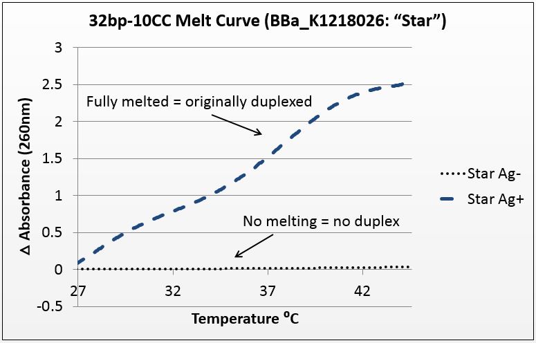
For this experiment, we sought to unequivocally prove that there was silver uptake by the excised duplex. To do this, we annealed the strands in two conditions: Ag+ (silver present) and Ag- (silver absent). The mismatch-complementary oligonucleotides in this sample were shown to only anneal in the presence of Ag+.
It is known that when double-stranded DNA is heated, it “melts,” or experiences a breakdown of its secondary structure. Beer’s law states that for a fixed volume and molecule, absorbance is proportional to concentration. As DNA melts, the concentration of nucleotides doubles, and the absorbance will increase similarly.
To show intercalation, we hypothesized that in this highly-mismatched strand, annealing will only occur in the presence of silver. Consequently, those strands should only show an absorbance increase with temperature if they were annealed with silver. That which does not anneal will not melt.
The graph below is the average of four trials, plotted for unit-less change in absorbance at 260nm (absorbance of dsDNA) over increasing temperature. The spectrophotometer we had access to restricted temperature to a maximum of 45°C, which we factored into the sequence design. 535 data points for each trial were taken across a 20°C temperature difference, rendering the ensuing data quite statistically significant.
Figure 1: average of four trials on 32bp10CC Star sequence, P value of 10^-272 in paired T-Test.
PAGE: electrical analysis of duplex formation
We utilized poly-acrylamide gel electrophoresis (PAGE)to produce visual representations of duplex formation, and we used this method to demonstrate that duplexing occurs as a 1:1 molar ratio between CC mismatches and silver ions is reached.
We tested undersaturation (<1:1 Ag:CC) and oversaturation (>1:1 Ag:CC) of the system, and showed the duplexing point. Duplexing became visually apparent at the 1.5:1 silver to mismatch ratio, which is slightly higher than expected. Nonetheless confirms both the role of silver in annealing mismatch-complementary strands and that the set point of the system is near a 1:1 ratio.
Figure 2: 10% polyacrylamide gel in MOPS buffer, 32bp10CC strand with increasing molarity of silver (inset above lanes); duplexing begins to be visible at 1.5:1 silver to mismatch ratio-- while this is not ideal, it demonstrates visually the duplexing as it occurs; duplexes are the bands above the rest, indicative of the size difference that comes with duplexing.
TEM: Visual analysis of particle pairing
We used transmission electron microscopy (TEM) to visualize our DNA directly. We hoped to directly identify the presence of silver in our samples. This was easier said than done, yet we used software to analyze the images that suggests that such a feat is possible.
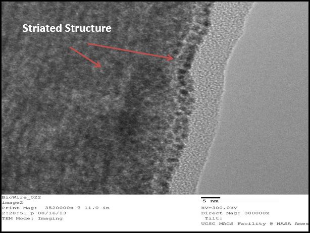
We used a sputtering technique to coat our samples with platinum ions. This allowed for a better visualization of the DNA, though it provided no analytical data (platinum masks the silver). We were excited by the striated nature of the DNA, again confirming that we were able to form duplexes. This DNA was supercoiled due to the sample preparation procedure, but was intriguing nonetheless.
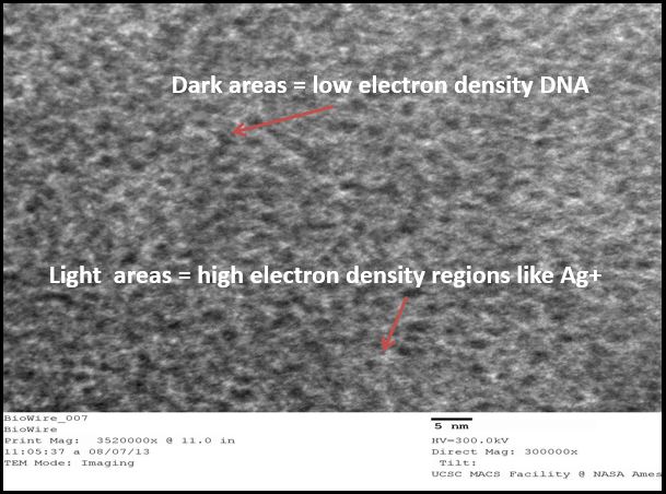
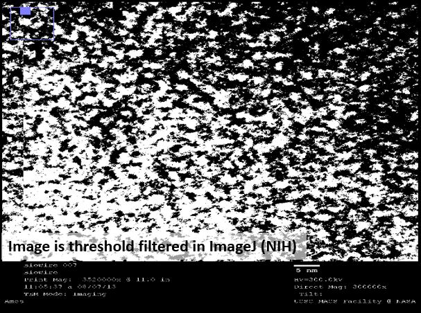
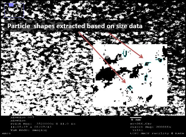
We then used a negative staining technique to visualize different samples to extract information about the structure of the strands. The high resolution images showed a mass of DNA, but we were able to analyze these images using ImageJ, an NIH-provided software for image analysis.
Under TEM, electron-dense areas such as silver are expected to shine brightly, while the low-electron DNA is expected to show up as a dark spot. BBa_K1218026 has a silver ion pattern of 2-1-2:
5’ AAA CAT TTA CCA CCT CCT CCA CCT TAT AGT TT 3’
   ||| ||| ||| ••| ••| ••| ••| ••| ||| ||| ||
3’ TTG TTA AAT CCT CCA CCA CCT CCA ATA TCA AA 5’
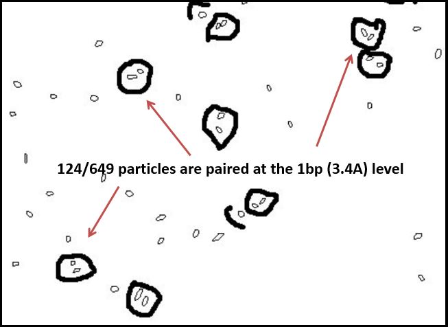
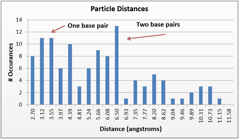
Thus, where silver is present inside the DNA, it should be at a known distance from other particles. With this in mind, we used ImageJ to find all particles within 30% of the silver ion size (2.4Å diameter, or 5.8Å2). We then measured the distance of the center of each particle from nearby particles. As expected, we saw local maxima at the distances representing distances of one and two base pairs (3.4Å and 6.8Å, respectively). We did this measurement manually using the software, and are in the process of using Matlab code to do the same process, albeit at a higher fidelity. Local maxima at integer multiples greater than two base pairs were not observed, likely due to the supercoiling of the DNA.
In sum, by using TEM, we were able to visually demonstrate the silver ion distribution across our samples, providing even further evidence of the robustness of our system.
Figure 3(a): Platinum sputtering TEM image of 32bp10CC strand (BBa_K1218026); of note is the striated pattern in the DNA; Figure 3(b): negative staining technique of different sample of 32bp10CC: dark areas are DNA, light areas are electron-dense areas; Figure 3(c): image threshold of 3(b) taken using ImageJ; Figure 3(d): particles delineated as ranging between 0.45 and 0.75 Å^2; Figure 3(e): paired particle counting of 3(d) using ImageJ and manual measurements, though rudimentary, the trend was strong: 124/647 particles were within 2.5-4.5 angstroms of one another, corresponding to roughly the length of one nucleotide.
Figure 3(f) Using a similar method but a tighter particle size (0.45-0.65 Å^2), distances between the centers of particles were counted and placed on a histogram; note local maxima at 3.4 and 6.8 angstroms, 1 and 2 bases in length, respectively.
| None |

